 The control panel.
The Millionaire is primarily a multiplying machine, not an adding machine, and is best described and understood from this perspective.
When we multiply (say) 7 by 6, the result is comprised of four tens and two units. The multiplication table that we have stored in our memory retrieves the answer as the single number 42. The Millionaire also contains a multiplication table, but differs in that it processes the tens and units for each digit separately. These "partial products" are combined in an accumulator register to display a single result.
When the Millionaire multiplies 7 by 6, its controlling mechanism refers to the internal multiplication table and returns the partial product 4 (tens). This is added to the register, which then moves one place to the left. The multiplication table then returns 2 (units), which is added to the register (now to the right of the tens) to display the answer 42. The machine requires only one turn of the crank for each digit of the multiplier, but makes two partial-product cycles for each turn - one for the tens, then one for the units.
The control panel.
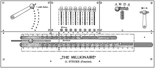
This drawing of the control panel is taken from an original Millionaire instruction manual. The panel measures about 640 x 260mm (25" x 11") and is divided into four sections:
The centre of the upper (rear) section contains the setting mechanism for the first factor. The slider mechanism includes a row of check dials to give a straight-line display of the setting.
The multiplier control lever at the left rear sets the second factor, one digit at a time, starting with the most significant.
The right-hand rear panel contains the "Regulator", which sets the mechanism to Add, Multiply, Divide, or Subtract (AMDS), and the operating crank. The crank is given one full turn clockwise for each machine cycle, until it comes to rest against a fixed stop in its home position. The crank must never be turned backwards.
The lower section of the top panel covers the moving carriage, which occupies most of the front half of the machine. The panel has two long openings to reveal the 16-digit accumulator register and the 8-digit counter. The knobs to the right of each register are pulled to the right to clear the display. The carriage is moved automatically to the left during multiplication and division, and is returned manually while pressing the knob at its left-hand end.
Millionaire calculating machines were made with either sliders or keyboard setting, with six, eight, or ten columns, with wooden or metal cases, with manual or electric drives, and with a variety of custom-built stands and tables. The most frequently encountered are the eight-column slide-set machines with manual drives and wooden cases.
 Internal view.
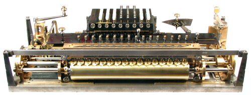
This view shows a key-set Millionaire mechanism with the case and top plates removed.
The controls shown in the drawing above are all visible, but most of the mechanism is hidden by the carriage at the front and the keyboard at the rear.
All of the components will be described in detail in the sections following.
 The basic mechanism.
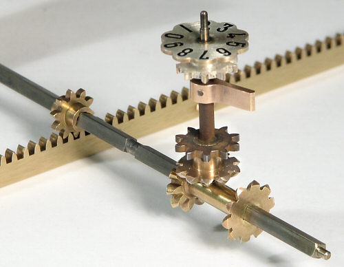
This view shows the essentials of the calculating mechanism.
There are ten sliding racks mounted horizontally at the rear of the machine. The movement of the racks is picked up by a pinion on a cross-shaft, and is transferred through the bevel gears to the register dial in the carriage.
The cross-shafts correspond to the columns of the setting mechanism. The racks correspond to the numbers set on the sliders (or keyboard). The distance moved by each rack is the product of the rack number and the setting of the multiplier lever, as determined by the multiplication table for the tens and units separately.
For example, setting a slider to 7 will engage its pinion with rack number 7. Setting the multiplier lever to 6 will cause rack 7 to move 4 places during the tens cycle, and 2 places during the units. (All of the other racks will also move according to the six-times table, regardless of whether they are needed or not).
Reversing the movement for subtraction is done by sliding the double "differential" gear along the cross shaft to drive the register's bevel gear from its opposite side. The differential gear moves to a central or neutral position to disengage the register while the racks are being returned to their home position.
(The term "differential" was widely used in the original literature simply to mean "different", as in driving the dial in different directions, or selecting different values from 0 to 9. It does not (in this case) refer to a planetary gearset or an automotive-style differential).
The mechanism will now be dis-assembled and its components described in detail.