 The multiplier unit ready for installation.
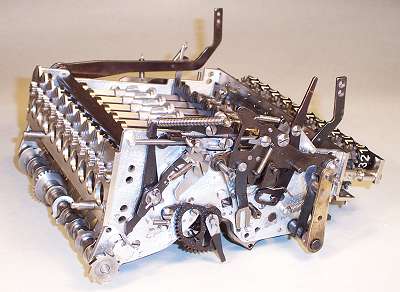
While the subtract-and-shift process of automatic division is essentially self-regulating, automatic multiplication requires the machine to store the first number entered, and then make the required number of addition cycles in each decade position. This process is controlled by the multiplier unit, a more-or-less self-contained module occupying the front half of the machine, between the two side plates.
The multiplier unit ready for installation.
A view of the multiplier from the left rear corner. It is held in position by the two pins at the rear, and two screws under the numeral register (Register V) at the front.
There are only two user controls - the "multiplier bar" mounted across the front of the machine, between the two larger arms, and the smaller vertical lever which selects whether the result is displayed in normal or complement mode. Later models replaced the lever with a separate "negative multiply" key to the right of the multiplier bar.
The multiplier unit is built from about 100 components and sub-assemblies, containing almost 600 individually manufactured parts.
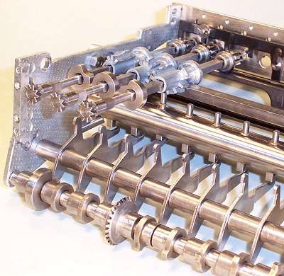 The stepped drums and pinshaft.
The multiplier unit (shown partly assembled) uses a second set of ten stepped drums to store the first factor in the calculation. The number is loaded by sliding the drum shafts rearwards (ie, towards the camera), so that the small gears engage with those on the addition unit. The shafts slide through the drums, which are held in position fore-and aft by collars on either side of the fixed rectangular bar. Once rotated into position, the multiplier drums store the number unchanged throughout the entire operation.
The camshaft at the bottom of the unit connects through the bevel gear to the rear-panel gears and the carriage sensing rack, so that the camshaft rotation is synchronised to the carriage position.
Each cam has a single projection, which operates via a long finger to raise a pin on the cylindrical shaft under the stepped drums. Hence for each carriage position, the corresponding pin is raised on the pin shaft. (The third pin is raised in the illustration).
In its home position, the pinshaft is rotated so that the tips of the pins are towards the camera and clear of the drums. When the pinshaft latch is released, the shaft rotates forward until the active pin hits the end of the lowest tooth on its drum. The distance that the pin moves corresponds to the number of addition cycles that are required for that decade. As the machine cycles, a ratchet moves the pinshaft back one step for each addition. When the pinshaft reaches its home position, a carriage shift is initiated, the camshaft rotates one step to raise the pin for the next decade, and the process is repeated.
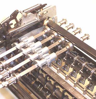 The two zero-detect mechanisms.
Just below the stepped-drum locating bar is a cross shaft with ten rigid vertical fingers. The disks on the front of the stepped drums have notches in their front faces at the zero positions (horizontally to the right in the photo). When all the drums stand at zero, the arms fall into the notches and the shaft rotates towards the rear. This "all-zero" mechanism toggles the function of the multiplier bar. If the register is zero, pressing the bar will engage a mechanism on the right-hand side to load the number from the keyboard into the multiplier. If the register is already loaded, ie non-zero, the bar will operate the levers on the left-hand side to initiate the multiplication cycle.
The second zero-detect mechanism is located under the notched disks towards the rear of the square shafts. This mechanism has a set of cascaded sensing fingers that can rise vertically into the notches at the zero position, provided that all digits to the left also stand at zero. The appropriate digit position is selected by the vertical fingers on the carriage camshaft levers (see previous photo for a better view of the notched disks and the selecting fingers). When the mechanism senses that all decades to the left of the current position are zero, it terminates the multiplication and returns the carriage to its home position. The automatic carriage return can be disabled by a small lever on the front of the machine, to the left of Register V.
The small gears near the front of the square shafts engage with the Register V clearing mechanism. The collars on these gears sit over a bail which slides the shafts rearwards to engage with the addition unit.
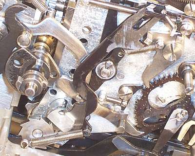 The pinshaft sector.
The ratchet sector which operates the pinshaft is in the lower right of this view. The operating lever is driven by the innermost cam on the mainshaft (shown here at maximum stroke), and pushes the pinshaft anti-clockwise towards its home position by one step for each machine cycle. The larger spring-loaded pawl at the top locks the sector at each step.
On the final step into the home position, the small pin on the face of the sector pushes forward on the arm which hangs from the sector pivot shaft, and initiates a carriage shift.
The ratchet wheel at the bottom left is attached to the carriage location camshaft. As each carriage shift is completed, this ratchet rotates anti-clockwise, raising and then releasing the forked lever at the top centre. This lever trips the sector locking pawl, allowing the pinshaft to spring forward into the starting position for the next decade.
When the multiplication is completed, the top of the forked lever is pushed rearwards so that it no longer reaches the locking pawl. The pinshaft remains locked in its home position, with the pins clear of the stepped drums. The mainshaft cam still operates on every machine cycle, but the sector operating lever strokes harmlessly against the "missing" tooth.