 The fun starts here...
These photos give a general outline of the order in which the Madas was re-assembled. This was not simply the reverse of dis-assembly, as many things became clearer once the pieces were more visible. Still, I doubt that the factory would have done it this way either...
The fun starts here...
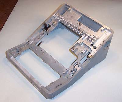
The Madas is built on a die-cast and machined light-alloy frame which varies from 4 to 9mm thick. The die-cast side covers (not shown) are lined with lead sheet for noise reduction.
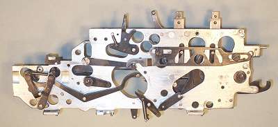 The right-hand side plate (inside).
The right-hand side plate measures 240 x 80mm and is 3.5mm thick. These inside levers need to be assembled before the plate is installed.
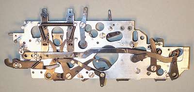 The right-hand side plate (outside).
The outside of the right-hand plate can only be partially assembled prior to installation. The main features are two vertical levers for the plus and minus keys. These push the long horizontal link forwards or back, positioning the differentials via the arm at the rear (right-hand) end.
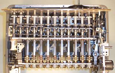
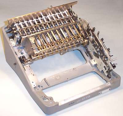 The add-and-carry mechanism.
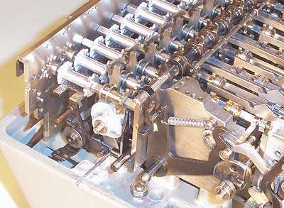
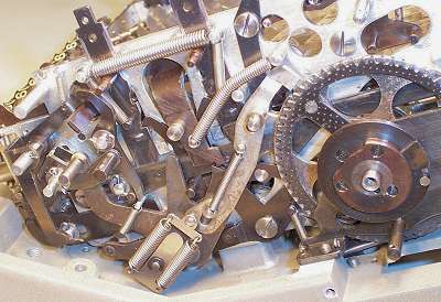
This photo shows the add-and-carry mechanism assembled in the rear half of the machine.
The stepped drum unit was installed first, minus the transfer shafts. Then the carry camshaft was installed, with a temporary bracket constructed to support its left-hand end. The right-hand side plate and the rear plate were then fitted, so that the shift-and-clear mechanisms in the right-hand rear corner could be assembled and tested. When all of this was working, the carry sense levers and the differentials locating rail were fitted. Finally, the transfer shafts, carry pinions, and differential gears were installed and the bearing caps fitted, after much fun with the detent balls.
Note that the teeth on the carry pinions and differentials must align with those on the detent gear, ie, space rather than tooth uppermost in the locked position.
The bevel gear visible in the central opening transfers the carriage position to the multiplier unit, via a rack-and-pinion on the rear plate.
 Top view of the add-and-carry mechanism.
The locating bar for the carry sense levers can not be fitted until the left-hand side plate is in place. Temporary measures are required to locate the carry pinions clear of the camshaft and operating fingers, so they do not foul as the machine is cycled. A metal strip about 8mm wide laid behind the pinions will keep them out of trouble.
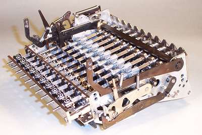 The multiplier unit.
The Multiplier unit assembled ready for installation. There are two pins of about 4mm diameter at the back, which slide into holes in the front plate of the add-and-carry assembly, and two screws into the base plate through the numeral register at the front. There are only a couple of springs and sliding links to connect the multiplier to the right-hand side plate.
The multiplier camshaft must be timed correctly to the carriage position during installation. There are timing marks on the rack-and-pinion, but none on the bevel gears.
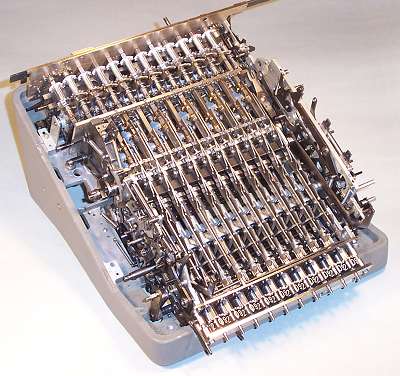 The multiplier unit installed.
This photo shows the situation after the multiplier unit has been installed. The links connecting the keyboard to the sliding pinions have been fitted, but the springs holding them into the zero positions are not yet in place (fitted later from underneath). Although these keyboard links look like they are going to be difficult, they fall into place quite readily. Although physically mounted to the multiplier unit, they take no part in the multiplier operation.
 Finishing the multiplier left-hand side.
Once the multiplier unit is in position, the pinshaft sector operating and trip levers can be installed. The cross-shaft which controls the automatic carriage shifts is then installed from underneath, and engaged with the hanging lever on the pinshaft sector.
 Preparing to fit the left-hand side.
This view shows the left rear of the machine before fitting the side plate. At the back is the bar which moves the differentials, with one of its operating arms underneath. The shaft protruding behind the carry fingers transfers carriage shift requests to the trip levers on the right-hand side. The counter register operating shaft is in position, along with its rocking lever resting on the mainshaft cam.
The temporary bracket supporting the carry camshaft must be removed at this stage, leaving the mechanism in a rather delicate state. If the camshaft drive gear falls out of engagement while fitting the side plate, the timing will be destroyed, and it's back to square 1...
 The left-hand side plate (inner).
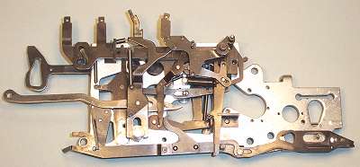
The inside of the left-hand side plate must now be prepared for installation. The slotted lever (top left) is the back-transfer lever, and below it is the keyboard clearing link. The two vertical key levers at the front are to clear the count and accumulator registers. The smaller lever is the keyboard repeat key (ie, it inhibits clearing the keyboard during multiply and divide), and the fourth is the divide setup key.
This sixteen levers in this assembly are seven layers deep.
 The left-hand side plate installed.
The side plate has been eased into position over the various shafts. The carry camshaft bearing has been fitted, and the carry sense lever detent bar has been installed.
The items in the previous three views are totally inaccessible once the side plate is installed.
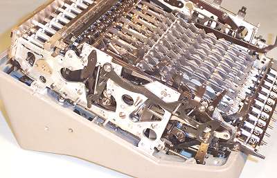
 The left-hand side plate completed.
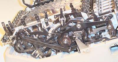
There are 30 separate links and levers, fitted six layers deep on the outside of the left-hand side plate.
Most of the left-hand levers are associated with the automatic carriage shifts that occur during set-up of multiplication, division, and back transfer operations.
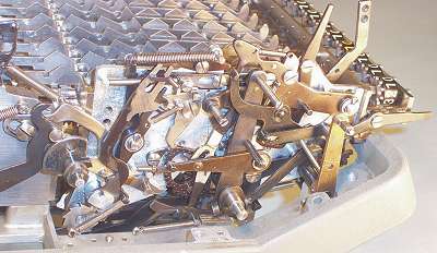
 The right-hand side brake assembly.
The brake arm at the front right-hand side of the machine (foreground) is attached at the bottom to a cross shaft which carries the motor switch operating arm. Rotating the switch shaft anti-clockwise raises the brake arm and starts the motor. At the end of a cycle, the head of the brake arm falls into a notch in the disk behind the main drive gear, and the rotational energy is absorbed in the springs.
The switch shaft can be operated by arms underneath and on the left-hand side of the machine, as well as via two rearward extensions on the brake arm itself.
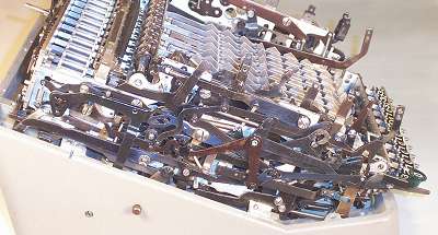
 The right-hand side plate completed.
There are about 35 links and levers on the outside of the right-hand side plate, arranged seven layers deep.
The front section is mainly the +/- and shift keys, and their various interlocks and releases. The rear section is mainly for the automatic division control.
 Finishing underneath.
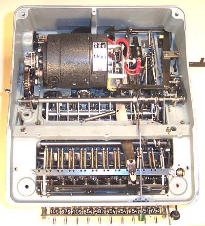
The shaft across the centre of the machine controls the automatic carriage shifts during multiplication and division, via a trip mechanism located towards the right rear.
The chain of four levers along the right-hand side transfers the motion of the clearing arm at the centre rear to the Register V clearing rack at the front.
The motor has a centrifugal clutch on the driving gear, and there is a friction clutch on the fibre intermediate gear. Although the motor is mounted on insulated bushings, the exposed workings of the centrifugal governor and the main switch carry full mains potential. The machine does not meet modern standards for electrical safety, and must be treated with extreme caution when power is applied during the final stages of adjustment and testing.
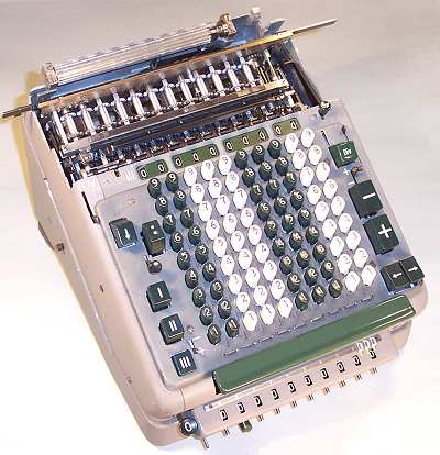
 Fitting the keyboard.
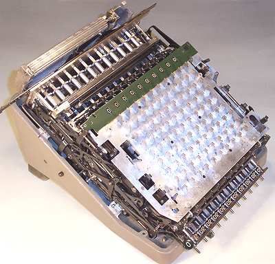
The keyboard is a self-contained module which is held in place by four small screws into the side plates. The only other connection is a shoulder screw attaching the keyboard clearing link.
The keytops are added next, but the key escutcheon plate can not be fitted until the side covers have been installed. (It is not necessary to remove the (push-on) numeral keytops unless the keyboard is to be fully disassembled for cleaning).
The "drum gear" which drives the Register IV camshaft has been fitted to the rear of the machine, and the rubber feet have been (temporarily) installed to keep the motor off the ground.
 Finishing off.
After installing the front and side covers, the key escutcheon plate and the key tops can be fitted. The carriage is fitted last.
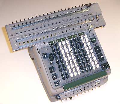 Completed.
With the carriage back in place the Madas is ready for another fifty years...