John Wolff's Web Museum
Victor 1800 Scientific Desk Calculator
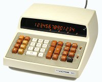 Victor 1800 Series, Model 18-1721, S/N 4676-666
Functions: ASMD, trig, log, powers, 1 memory
Technology: MOS-LSI (Rockwell, 6 chips)
Display: 14 digits, 7-segment neon (Panaplex)
Dimensions: 250W x 290D x 130H
Weight: 2.78kg
Manufactured: Victor Comptometer Corp, Chicago, 1973
The Victor Comptometer Corporation (formerly the
Victor Adding Machine Company) sold a
range of attractive and functional desktop calculators under the
"Victor 1800" label from around 1971.
The Model 18-1721
illustrated is a "scientific" calculator
that was built in mid-1973. It provides trig and log functions and
their inverses, powers (including fractional and negative), square
roots, and reciprocals. It operates in degrees or radians, and in
common or natural logarithms, and has a single (accumulating)
memory register.
This page gives a brief description of its construction and
operation.
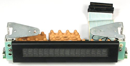
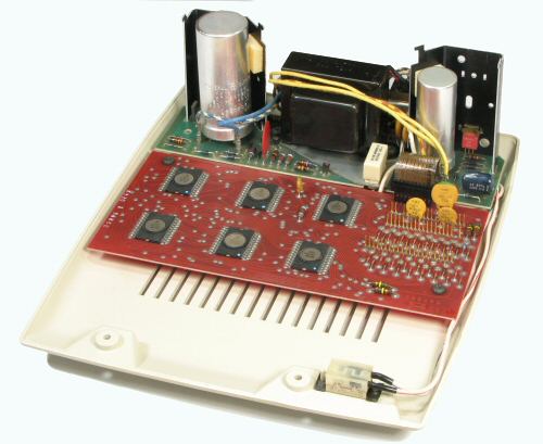 Internal view - base section.
The calculator has a simple but attractive two-part plastic case.
The base section contains the power supply at the rear and the
logic board in the centre.
The power supply is built on a 9" x 2-1/2" board. A metal bracket
under the transformer supports a standard US mains input connector
and a voltage selector switch. The mains input is rated at 115/230V,
50/60Hz, 18W. The power switch is under a recess at the right-hand
front corner.
The components on the right of the transformer produce the
positive and negative logic supplies, while those on the left produce
-175 and -225V for the gas-discharge display.
The logic board measures 9" x 4-1/4" and carries six Rockwell
LSI chips in 42-pin packages. The right-hand section of the board
has four rows of header pins which connect to the power supply,
keyboard, and display via flat ribbon cables. There are very few
discrete components (apart from a diode array near the keyboard
connector), and no hard-wired off-board connections.
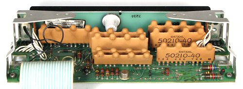
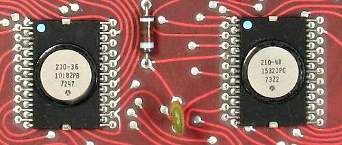 Logic board detail.
This view shows two of the six chips on the double-sided phenolic
logic board.
The chip numbers and date codes are: 10177PA/7311, 10178PA/7314,
10179PB/7308, 10180PA/7245, 15320PC/7322, and 10182PB/7247.
The date codes range from October 1972 to May 1973.
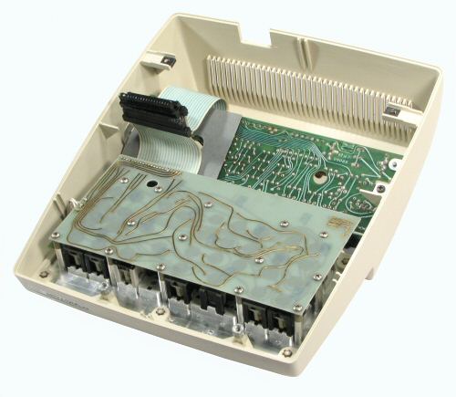 Internal view - top section.
The top section of the case contains the keyboard and the display
module. The display is attached to the top and sides of the case with
four screws, but the keyboard assembly is permanently heat-staked
in place.
Connections from the keyboard and display to the logic board
are made through three flat-ribbon cables. An additional insulating
sheet is fitted between the ribbons and the underside of the display
module. There is a separate earth wire from the power supply to the
metallised underside of the keyboard assembly.
Care must be taken when removing the top cover, as the ribbon
cables are short and rather inflexible. The cover must be lifted
vertically to avoid bending or breaking the header pins.
 The display module.
The gas-discharge display and its high-voltage drivers are
assembled into a self-contained module supported on two sheet-metal
brackets.
The display is a Burroughs "Panaplex", model BR-16401, which
measures 7-1/2" x 1-1/2" x 3/8" thick. The display has 16
seven-segment numerals, approximately 7/16" high, on 3/8" centres.
The leftmost digit is used for error and overflow indication and the
rightmost for polarity, leaving 14 for the numerical display.
There is a small incandescent lamp at the top right-hand corner
which lights when the memory is active.
 Display module - rear view.
The high-voltage drivers for the Panaplex display are packaged
in eight sealed hybrid modules and mounted on a 9" x 2-3/4" board.
There are two 19-way ribbons connecting to the logic board.
The Panaplex display has a date code of 7234 (September 1972).
 Key sheet.
The elastomeric keyboard has individual conductive discs
attached to a thin (0.002") key sheet.
The key switch mechanisms press down on the discs to form a
connection between pads on the gold-plated circuit board below.
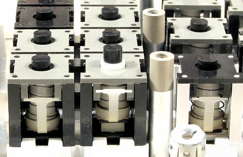 Key switch mechanism.
The key switch mechanisms are individual plastic assemblies
which clip into the moulded key frame. This view shows the under
side, with the circuit board and key sheet removed. The front
centre key is shown in the pressed (raised) position.
The key switches have a double spring mechanism which limits the
force which can be applied to the key sheet. The white key stems come
to a positive stop before they reach the key sheet. The operating
force is applied by the black contact button, which has a separate
light spring inside the key stem.
The "T" arms attached to the sides of the keystems ride on the
adjacent cam blocks to provide an over-centre feel to the key
movement.
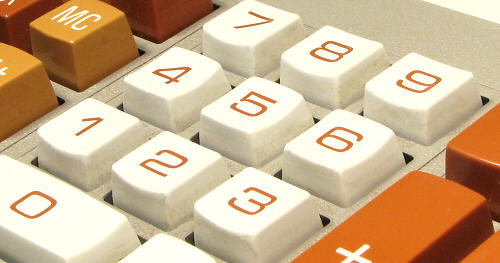 The key tops.
The tops of the numeral keys are contoured, with the depressions
in alternate rows aligned vertically and horizontally.
The function keys all have flat tops, and are taller than the
numeral keys.
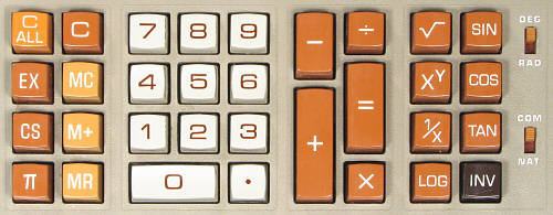 The keyboard layout.
The keyboard is arranged in a clear and logical manner, with the
numeral keys in the centre and the function keys on either side.
The function keys are colour-coded in three shades of tan.
The two slider switches are at the right-hand side, adjacent to
the functions they control.
Operation
The machine powers up with the display showing a single zero at
the right-hand side. The display is always right-aligned, with
leading zeros blanked and trailing zeros removed.
Addition and subtraction work in adding-machine fashion,
displaying the running total without using the Equals key.
Multiplication and division work in algebraic fashion. Results are
displayed to a maximum of 14 digits, with a floating decimal point
and no roundoff. Overflow or error conditions show "F" in the
leftmost position.
With the exception of the XY key, the function keys on
the right-hand side are pressed after their arguments and
produce their results without using the Equals key. Square roots and
reciprocals are displayed almost instantaneously. Trig and log
functions take just over 2 seconds, with intermediate results
flashing rapidly on the display. Two slider switches to the right
of the function keys set the machine for degrees or radians, and for
common or natural logarithms. The INV key is used between the
argument and the trig or log key to calculate the inverse.
The XY key calculates positive or negative powers of
positive arguments. The key sequence
X, XY, Y, = appears to be a
"shortcut" for X LOG MULT Y INV LOG, and
produces identical results.
There is a 2-second delay on pressing the power key as the machine
calculates log X and stores it in an (inaccessible) internal
register, and again as the inverse log is calculated on pressing the
Equals key.
On the left-hand side of the keyboard, the π key enters the
value to 14 figures, while the CS key changes the sign of the display.
The three memory keys work as expected, with M+ adding the
displayed value to the existing memory contents. An indicator light
at the top right of the display shows when the memory is active.
In addition to the memory function, the calculator has a separate
buffer register which can be accessed for additional temporary
storage. The EX key exchanges the contents of the display and the
buffer. The buffer is overwritten by the first factor of a
multiplication or the second of a division, but is otherwise
available for use.
The C key clears the display, while C ALL clears the display, the
memory, and the internal buffer.
Original text and images Copyright © John Wolff 2006-18.
Last Updated: 15 April 2018
Back to:
Home
Calculating Machines
Early electronic calculators
Victor
 Victor 1800 Series, Model 18-1721, S/N 4676-666