Contents
Contents |
|
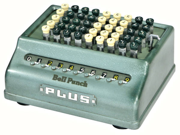
| PLUS Model 509, 1950s |
The "PLUS Rapid Adder" is a compact key-driven adding machine with an abbreviated or "half" keyboard.
The original mechanism was designed by Guy Petter of the Petter oil engine family during the 1920s. The design was acquired by the Bell Punch Company in 1936, and was put into immediate production. A greatly improved mechanism was developed by Christopher Webb of Bell Punch in 1938, and remained basically unchanged through all the subsequent models. Production ended in the early 1970s.
The notes and illustrations following describe the internal mechanism and operation of a typical PLUS adder. The machine illustrated is from the 1950s, but the notes are applicable with only minor variations to any of the post-1938 models. (The early Petter machines are easily identified by their black bakelite rather than die-cast casing. They are not often found).
Please refer to the Bell Punch Company page for further details and illustrations of the PLUS model range.
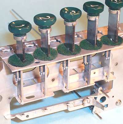
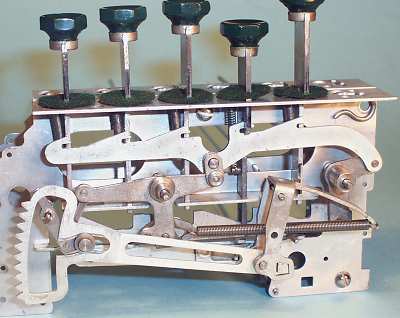
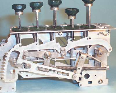
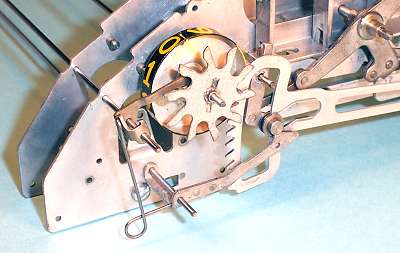
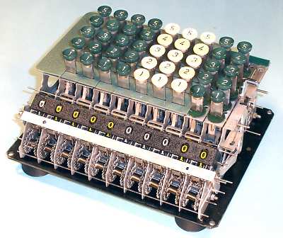 Overview with covers removed.
Looking fore-and-aft, the front third of the PLUS mechanism consists of a numeral-wheel register and its associated tens-carry mechanism. The rear section contains the keyboard and the actuating mechanism. The actuating mechanism is completely disengaged from the register when the machine is at rest.
From side to side, the mechanism consists of 6, 9, or 12 more or less identical columns, referred to as "lines" by the manufacturers. The lines have pressed-metal side plates held together by four 1/8" threaded rods and metal spacers. There are thirteen rods or wires of 1/16" diameter and two of 3/32" which pass through all of the lines and act as pivots and retainers for the mechanism. The whole assembly is fastened to a heavy base plate of 0.100" steel (weighing almost 2 pounds), and covered by a die-cast metal housing.
Each line raises a toothed sector as the key is pressed, and engages it with a pinion on the numeral wheel at the end of the keystroke. The numeral wheel advances by the corresponding number of digits as a spring returns the line to its rest position on the return stroke. Each line operates independently, except for the carry mechanism which transfers the tens from one column to the next. A "duplexing" or carry delay mechanism allows adjacent lines to be operated simultaneously. The left-most column has no keyboard mechanism, but has a register to accumulate carries from the lower orders.
The lines are all identical on this decimal-currency (base 10) machine, but versions for different unit systems could be made by changing the gearing on the sector and the register mechanism. Lines were built with base 12 for pence or inches, base 6 for minutes and seconds, base 4 for farthings, and base 2 for ten-shillings. Less common versions were made for other units, including even tons, hundredweight (base 20), and quarters. The keyplate was made in sections that could be interchanged to accommodate the differing key arrangements (the right-hand sections have been removed for this illustration).
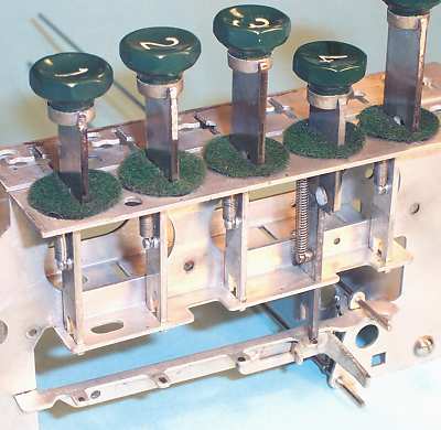
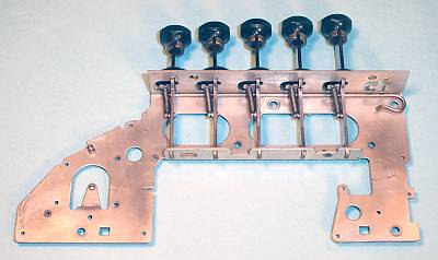 The side plates and keystems.
The line mechanism for each column is sandwiched between pressed-metal side plates of 0.040" steel. All the plates are identical, except for the right-most which is modfied slightly to accommodate the clearing mechanism.
The moulded keytops are fitted with metal collars to prevent splitting as they are pressed and crimped on to the flat metal key stems. Individual felt washers are fitted to each key stem to retain lubricant and exclude dust.
The key stems are installed through the top of the plate and supported by individual return springs. The wire "shepherd's crook" is inserted above a shoulder on the keystem to retain the keys and limit their upward motion.
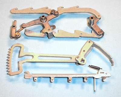 The line levers.
This view shows the three major components of the line mechanism.
The main parallelogram linkage (top) is a single component made up from 26 separate manufactured parts. Its primary functions are to control and limit the motion of the keys, and to raise the toothed sector lever (centre) by the corresponding distance.
The sector lever assembly is hinged at its "elbow", and is mounted on a pivot at the apex of its rear section. This enables the sector itself to move both vertically and horizontally.
The vertical motion is controlled by the flanged lifting roller at the bottom front of the main linkage, which engages with the ramped slot behind the sector teeth.
The horizontal motion is controlled by the long operating finger on the sector trip bar (bottom), which engages with the stepped slot behind the elbow of the sector lever.
 The sector trip bar.
The sector trip bar is mounted across the gap in the side plate, directly below the keys. It is located via interlocking slots at the front and a slot-and-tab arrangement at the rear. It is retained in position by a 1/16" wire rod through the vertical tab at its rear end.
A spring (located just behind the side plate) holds the trip bar counter-clockwise, with the operating finger on its right in the raised position. A second wire secures the lower end of the spring.
 The sector trip bar and keystem.
When any key reaches the bottom of its stroke, it contacts the corresponding short tab protruding from the right-hand side of the sector trip bar and pushes the operating finger downwards.
Observe the shape of the keystem on the depressed key, and note particularly the shoulder on the right-hand side, the adjacent hole, and the vertical slot in the bottom. These features are significant in the next section.
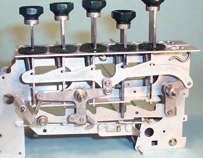 The line linkage installed.
The parallelogram linkage is carried on two 3/32" pivot wires, with the sector lifting roller on a third 1/16" pivot at the front.
As the key is pressed, the shoulder on the right of the keystem presses downwards on the small flats on the top of the upper link, just behind the rearward-facing "hooks". The upper link initially moves rearwards as well as downwards, so that the hook engages with the hole in the keystem. This couples the two together, and also prevents any other key from engaging until the line has completely reset.
As the upper link moves downwards and rearwards, the lower "sawtooth" link moves forwards, passing through the slot on the bottom of the keystem.
The short vertical link between the upper horizontal link and the central "T" lever distorts the parallelogram slightly, so as to give progressively more travel for the longer keys. The key travel varies from 13/32" for the 1 keys to 15/32" for the 5s.
As the line operates, the front of the central "T" lever rises, raising the sector lifting roller (bottom left) via the light intermediate link.
 The sector lever and mainspring.
The sector lever assembly is mounted on a single 1/16" pivot wire located between the two main linkage pivots. The slot near the front of the lever engages with the lifting roller on the main keyboard linkage.
The front of the mainspring attaches to a hook on the lower arm of the central "T" lever, holding the mechanism in its rest position (as shown).
The rear of the mainspring attaches to the tail of the sector lever assembly, and attempts to push the sector forward into engagement with the numeral wheel pinion (hidden behind the large star wheel). However the raised finger of the sector trip bar is latched in the slot behind the "elbow", thus holding the sector lever rearward and clear of the pinion.
 The sector lever at mid-stroke.
As the key descends, the central "T" lever is rotated clockwise, raising the sector lever via the lifting roller in the slot.
At the same time, the lower sawtooth link is moving forwards towards the keystem, and the mainspring is being further tensioned.
 Full stroke and return.
The line mechanism reaches a positive stop when the vertical edge of the forward-moving sawtooth strikes the rear face of the descending keystem.
At the same time, the bottom of the keystem reaches the short tab on the side of the sector trip bar, and presses its operating finger downwards. This releases the latch at the sector assembly elbow, and allows the sector to spring forward into engagement with the pinion on the numeral wheel.
The tabs on the sector trip bar are adjusted after assembly (by bending them slightly, from underneath) to ensure that the keystem stop and the sector release occurs smoothly and evenly on all keys. The forward motion of the sector is also adjusted by a stop tab on the underside of the sector trip bar, so as to ensure that the sector meshes correctly with the pinion without binding.
When the operator releases the key, the main spring pulls the line mechanism back to its rest position, advancing the numeral wheel by the corresponding number of places. At the very end of the stroke, the lower pin on the inverted "L" lever at the rear of the parallelogram lifts the tail of the sector lever assembly. This movement pulls the sector rearwards, disconnecting it from the numeral wheel pinion. The operating finger on the sector trip bar springs up into its forward slot, latching the sector lever rearward and clear of the numeral wheel.
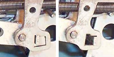 The sector trip latch (detail).
The left-hand view shows the sector lever latch in the "normal" or rest position. The sector lever is being pushed to the left by the mainspring, but is restrained by the raised finger of the sector trip bar.
The right-hand view shows how the sector lever moves forward when the latch is released at the bottom of the keystroke.
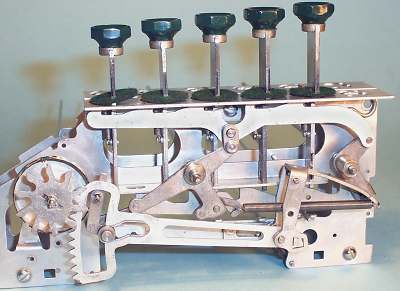
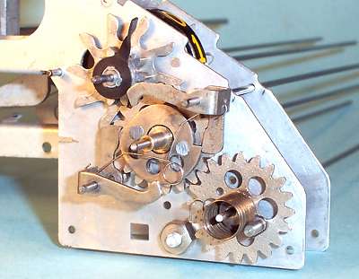
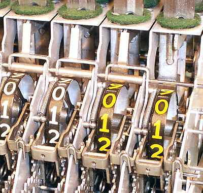
 Overview of the register mechanism.
This view shows the general arrangement of the register on a decimal machine.
To understand the operation of the register and carry mechanism it will be necessary to examine the components separately, and then look at how they are assembled on the right and left-hand sides of each line.
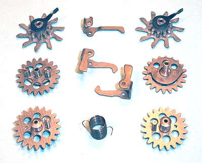 The register components.
This view shows the main components of the register and carry mechanism for a decimal line, laid out in their approximate positions.
Following the sequence of operation clockwise from the top right we have:
 The pinion detent pawl and spring.
The pinion detent pawl is pivoted near the front of the register and is shaped so as to prevent any possibility of reverse motion of the numeral wheel pinion.
Early Plus models used a simple coil spring on the detent pawl. This model uses a hairpin spring and lever assembly operated by the sector lifting roller. This mechanism reduces the detent pressure while the line is in operation, and also provides a spring-loaded buffer for the sector at the end of its return stroke. A stop (not shown) limits the upward travel of the spring lever to maintain an adequate minimum detent pressure.
 The pinion and cam gear.
This view shows the driving-side components of the tens transmission assembled on the right-hand side of a line.
The finger on the pinion assembly fits into a slot between 9 and 0 on the numeral wheel (removed for clarity). The 10-tooth pinion drives the 20-tooth cam gear, which drives the spring winding gear as the numeral wheel advances. The cam gear rotates clockwise in this view.
The two identical transfer pawls are arranged symetrically on opposite sides of the cam gear. They are interconnected by a light hairspring, which holds the short legs against the cam.
The gears are timed as shown in the illustration, so that as the numeral wheel passes from 9 to 0 (generating a carry), the cam will release the transfer pawl. The pawl is reset by the time the second pawl is released half a turn later.
The cam gear rotates at half the speed of the pinion, releasing and resetting the two pawls alternately every time the numeral wheel passes from 9 to 0.
 The transfer gear.
This view shows the components assembled on the release side, looking towards the left of the machine.
The transfer spring is given two full turns pre-load before assembly, and is tensioned by another half-turn as the numeral advances towards 9. The spring connects to the release gear (bottom left), which attempts to turn the transfer gear anti-clockwise.
The cam gear on the opposite side of the line will be holding the short leg of one of the transfer pawls outwards, so that the longer leg will be forced inwards. This leg will catch the finger on the transfer gear and block its rotation.
When the numeral wheel passes from 9 to 0 (generating a carry), the cam gear will release the pawl. The shaped finger pushes the pawl aside, and the transfer gear will be driven around by the spring until the finger strikes the second pawl. The two pawls operate alternately as an escapement, allowing the transfer gear to rotate half a turn each time a carry is required.
The two pins on the far side of the transfer gear extend through the side plate and into the path of the large star wheel on the next numeral wheel pinion. While the transfer gear is held against the pawl, the pins are aligned as shown in the illustration, so that they do not interfere with the star wheel's movement.
When the transfer gear is released and rotates half a turn, one or other of the pins will engage with one tooth on the star wheel and will advance it by one position. The star wheel is shaped as a "Geneva wheel" to ensure that there is no over-run.
 The transfer delay (duplexing) levers.
The line mechanism can not accept a carry from a lower order if it is already in operation due to a keystroke. A means must be provided to delay an incoming carry until the keystroke has been completed and the line has returned to rest.
This is the function of the duplexing levers, mounted on the pivot wire just above and behind the numeral wheels. (There is no lever on the rightmost line, as there are no incoming carries to this position).
The duplexing lever is spring-loaded so that its upper arm rests on the front end of the upper arm of the keyboard parallelogram linkage (visible in the rightmost column), and follows it rearward when a keystroke is in progress. The lower arm of the lever curves down into mechanism and moves into the path of the pins on the transfer gear.
If a carry occurs while the line is in motion, the transfer gear will be released by the pins but will be blocked by the duplexing lever. When the line retuns to rest, the top of the duplexing lever will be pushed forward, releasing the lock and allowing the delayed carry to take place.
Note that the line which generated the carry is not affected by the delaying mechanism, and will continue to operate while the carry is pending. However, it will block if a second carry is required before the first has been completed.
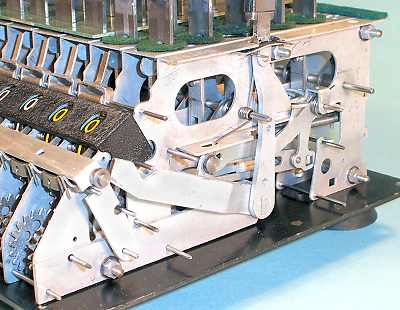 The clearing mechanism.
The vertical clearing lever on the right-hand side of the machine is attached to a 1/4" shaft through the base. This shaft is attached to inclined levers on each side of the machine, which in turn operate a clearing bail through small rollers (centre front, just below the register mask). The bail normally rests against the small tabs on the fronts of the pinion detent pawls. As the clearing handle moves forward, the bail presses downwards on the tabs and releases the pinion detents.
Recall that the carry gear train is under constant tension from the transfer spring. It is held on the left-hand side by the transfer gear and pawls, and on the right by the pinion detent pawl. When the pinion detent is released, the spring drives the right-hand gears backwards until the step on the cam gear stops behind one of the transfer pawls. This step corresponds to the transition from 9 to 0 in the forward direction, and so the numeral wheel stops at zero when released.
The clearing lever does not return immediately, but remains latched in the forward position. A multi-fingered lever under the machine senses the movement of the keyboard mechanism, and releases the latch on the first keystroke of the next calculation. The release provides an obvious "start-from-clear" indication for the operator.
Timing the carry gears.
When re-assembling the register mechanism, it is necessary to ensure the correct timing of the carry gear train.
On the right-hand side, the pinion and cam gear must be set so that the transfer pawl trips as the numeral wheel reaches zero. Fit the register mask temporarily to make sure that zero is in the right place.
The transfer spring is assembled to its winding and release gears and given two turns pre-load before installation. Ensure that this pre-load is not lost as the timing is adjusted.
On the left-hand side, the gears must be set so that the pin on the release gear is just below the pin on the winding gear when the register is cleared. The actual location of the pins does not matter, although the factory set them as shown, on either side of a horizontal line through or just above the gear centres. The important thing is that the pins must not be touching - the spring tension must be held between the transfer pawls when the pinion detent is raised, and not between the gear pins.
The purpose of the overlapping gear pins is to prevent incorrect results from mis-operation involving multiple outgoing carries. If a key is pressed and held, the transfer gear will be blocked by the duplexing lever. The winding gear can continue to advance (clockwise viewed from the right) until its pin approaches the release gear pin from underneath. The pins will block the mechanism when the numeral wheel reaches about 8 on the second revolution, rather than allowing (and losing) multiple carries.
The Plus adder could be supplied for use in many different units of measurement. Variations were manufactured for Sterling and decimal currencies, hours and minutes, feet and inches, and even tons, hundredweight, and quarters. This section describes the register gearset of a Sterling currency machine, and gives some idea of the complexities involved.
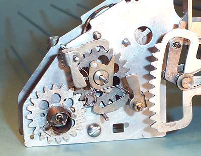
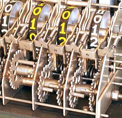 The Sterling gearset
This view shows the ten-shillings, shillings and pence gearsets on a Sterling-currency machine. (Note that the pinion detent levers on this early machine are fitted with coil springs, instead of the torsion springs used on the later models).
The numeral wheel for the pence column has 12 places, numbered 0 to 11. On the winding side, there are 12 teeth on the pinion instead of 10, and 24 each on the cam gear and winding gear. The gears (and the sector) have a finer pitch in order to keep the same diameters and centres. The release side uses the standard 20-tooth release and transfer gears. Both sides work half a turn at a time, so the actual numbers of teeth do not need to match.
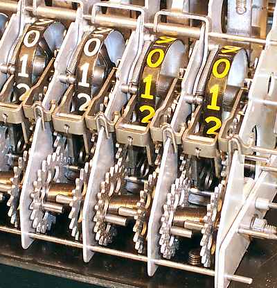
The shillings column is standard decimal, but the ten-shillings is rather different. The sector and pinion have the normal 10 teeth, and the numeral wheel has 10 places, but it is marked with five sets of 0 and 1. A carry must be generated after every two places rather than every 10. This is achieved by providing the cam gear with the normal 20 teeth (to mesh with the 10-tooth pinion) and a 5-lobed cam.
The winding gear is given 10 teeth (on the standard pitch), so that its two-place movement between trips is only 1/5 of a turn. This smaller 10-tooth gear requires a separate one-section shaft, which is held in place by a flat bronze spring clip over the side plate. The main spring-gear shaft is also cut on either side of the ten-shillings column and secured with two more clips.
On the release side, the gearing must be arranged to give half a turn of the transfer gear for 1/5 of a turn of the release gear. This is accomplished with a release gear of 25 teeth and a transfer gear of 10 teeth, where each gear moves 5 teeth at a time. The gear pitch is calculated so that the centres match those on the winding side. The carry spring is given a greater pre-load to overcome the 1:2.5 step-up ratio.
The Plus mechanism went through many minor changes and improvements during its 40-year history. This page shows a few of the variations that may be encountered - often within the same machine!
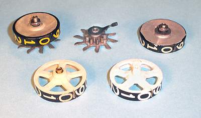 Four versions of numeral wheels
The older version at the top left has a threaded boss on the pinion assembly, with the aluminium numeral wheel disc attached by a nut and spring washer.
The other three versions all use a 3-part pinion assembly (top centre) with a separate numeral wheel. The pinion assembly is solidly crimped together and can not get out of alignment.
The numeral wheel at the top right is pressed aluminium with a threaded steel boss. At the front are two plastic versions, one with a brass insert and one without. The finger on the pinion assembly engages with the slot between 0 and 9.
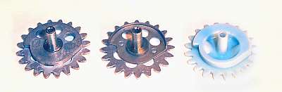 Three versions of the cam gear
Cam gears with (left to right): solid metal cam, sheet-metal cam, and all-plastic cam.
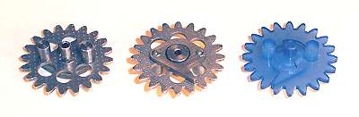 Transfer gears in metal and plastic
This view shows both sides of an all-metal transfer gear, and the later see-through plastic version. The all-metal gear was also made with a sheet-metal rather than solid finger. The carry spring gears were also made in several metal and plastic versions.
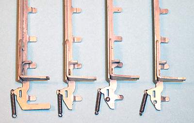 Four versions of sector trip levers
The version on the left has an extra arm at the bottom which serves no useful purpose in any machine examined to date. In the other versions, a separate manufacturing operation has been introduced to shear off the harmless but unwanted part.
In the third version, a small rivet has been added next to the slot,
to act as a pivot point for the lever. The rivet has been deleted in
the fourth version, but the hole remains. The remnants of the mystery
arm did not finally disappear until the late-model machines of the
1960s.
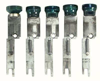 Five versions of "1" keys
In the late 1950s the PLUS keytops changed from octagonal (left) to round (second). The crimped keystems and metal collars were deleted, while the base of the keytop was increased in diameter to provide extra strength. This increase in diameter, when combined with the movement in the new soft rubber mountings, sometimes allowed the fronts of the "1" keys to hit the front lip of the casing and fail to register.
One solution to this problem was to mould new "1" keys (third) with a cut-away section at the front to clear the casing. Another (fourth) was to use the slightly longer keystem from the "2" keys for the front row as well. This upset the regular gradation in key height, but apparently was considered acceptable. Other machines have been found in which the "1" keys have both cut-away keytops and longer keystems (far right).