Contents
Contents |
|
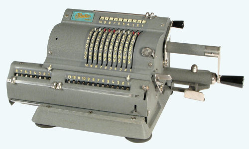
| Multo Model 113, c.1956 |
This page gives a brief technical description of the internal mechanism of the Multo pinwheel calculator.
The Multo calculator was introduced by the Addo company of Sweden in 1949 to supplement their traditional line of adding and listing machines. It was discontinued when Addo was absorbed into the Advidaberg/Facit/Odhner group in 1966. The Multo Model 3 is a basic machine which includes a setting check dial, while Model 113 also includes a back-transfer mechanism and tens-carry with automatic reversing on the counter register. Both versions are designed for one-handed operation, with all of their controls located on the right-hand side.
Readers unfamiliar with the principles of the pinwheel calculator may find it helpful to review the following pages before proceeding:
Readers interested in further details, or who may be planning to restore a Multo 3 or 113 to working order, will find a step-by-step procedure in the section on rebuilding.
I would welcome your feedback, comments, or suggestions for improvement via the enquiry form.
 General arrangement.
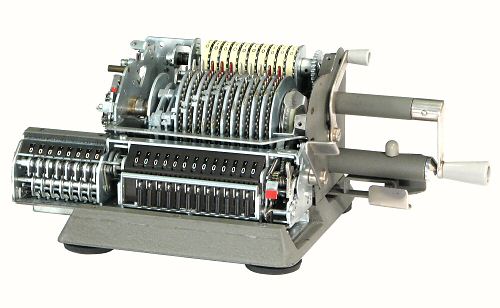
This view shows the Multo 113 mechanism with most of the external covers removed. (The right-hand end cover can not be removed while the end plate is attached to the base).
The machine uses a conventional Odhner-style layout, with the pinwheel rotor near the centre, the check dial behind, and the moving carriage at the front. The 8-digit counter register is at the left of the carriage, and the 13-digit accumulator at the right.
All of the operator controls are located on the right-hand side. The lever at the top rear clears the rotor, while that on the carriage clears both the registers. An adjacent small lever temporarily disconnects the accumulator so that the next stroke of the main lever will clear only the counter, as in setting up a division. The back-transfer is engaged by a push-button on the main body, and can be released manually by a small lever on the carriage.
The carriage is supported on rollers and is spring-loaded towards the left. It can be moved one step in either direction by the double-sided lever under the winding handle, or it can be run fully to the left by pressing rearwards on the dome nut on the handle stop pillar. The carriage can be pushed manually to the right whenever the winding handle is in its stop.
The Multo is quite heavy (6kg) and solidly built, with the base and right-hand end plate of cast iron. The pinwheels and check dials are of die-cast alloy, while the remainder of the mechanism (including the carriage frame) is of pressed metal. The external covers are of painted aluminium.
 The rotor assembly.
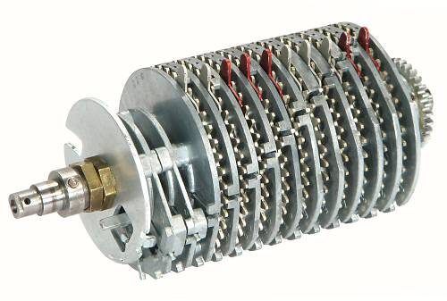
The Multo rotor has ten die-cast pinwheels of 65mm diameter, with the setting rings on 7mm centres. Three additional discs at the left-hand side extend the tens-carries across the full 13-place accumulator.
The rotor components are keyed and clamped onto a central shaft. The shaft has a driving gear, non-return mechanism, and carriage locking cam at the right-hand end, and a rotational locking disc at the left.
The setting rings have a continuous gear around the outside to engage with the check dial mechanism on the rear panel. The bar extending through the leftmost disc locks the rings by blocking the movement of the internal detent pins. The bar is pressed inwards to release the lock when the rotor returns to its home position.
 The rear panel and check dial.
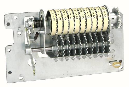
The check dials are 30mm in diameter, and are permanently engaged with the setting rings via the intermediate gears. As the setting rings rotate through 90° from 0 to 9, the check dials rotate through 180° to display the corresponding numerals. As the calculation proceeds, the check dials make two full turns for each turn of the rotor, always returning to the same positions.
The check dial shaft has a conventional clearing rack, operated from the rotor clearing handle via the gear at the right-hand end. As the shaft rotates 180° clockwise it is cammed to the right by a ramp at the left-hand end, engaging the internal clearing teeth and returning the dials and setting rings to zero. The shaft returns anti-clockwise to its home position as the handle is released - it does not make a full rotation.
The cam and lever at the left-hand side engage the rotation lock on the rotor end plate while clearing is in progress.
 The base and shift mechanism.
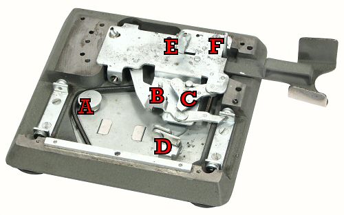
This view shows the carriage supporting rollers and the shift mechanism mounted on the base.
The long coil spring passes around the pulley at A and connects to the right-hand end of the carriage. The carriage is pulled to the left by the spring, but restrained by pawl B which engages with a toothed rack on the underside. Pawls B and C operate together as an escapement to let the carriage step to the left when the handle is pressed forward.
Pawl D is normally held inactive under a small ramped arm on the bottom cover plate. If the shift lever is pressed rearward, the pawl rises to engage with a second rack on the underside of the carriage and pushes it one step to the right.
The forked lever at E is operated by a long shaft through the handle stop to lock the shift mechanism when the winding handle is away from its home position.
Lever arm F is operated by the dome nut on the handle stop to release the escapement and allow the carriage to run fully to the left.
The shift mechanism can be removed from the base with three screws, but the levers and pawls are all permanently rivetted together and can not be disassembled for cleaning or repair. There is no provision for adjusting the lateral alignment of the carriage and the pinwheel rotor.
 The accumulator register.
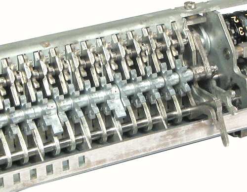
The accumulator register is quite conventional. This rear view shows the star wheels, carry levers, and the back-transfer gearset. The numeral wheels and their detent levers are hidden.
The carry levers each have a separate latch or detent lever which connects to the row of coil springs along the front of the register (visible in the first illustration above).
The back-transfer gearset is lifted into engagement with the rotor by a lifting bail in the main body of the machine, which acts on the two lugs at columns 4 and 8. (Note that the rear faces of the carry levers in these positions are shorter to provide clearance). The gearset is held engaged by a latch and indicator flag at the right-hand front of the carriage. The latch is released automatically at the end of the back-transfer operation, or it can be released manually if engaged in error.
The row of holes at the lower left of the illustration receive a sliding bar which locks the carriage position. The bar (at the bottom of the right-hand side plate) is cammed forwards whenever the rotor is away from its home position.
The first of the three levers extending rearwards at the far end of the accumulator operates the overflow bell. The second engages the rotor rotational lock when the back-transfer gearset is engaged, and the third (forked) lever engages the rotational lock during register clearing.
 The back-transfer lifting mechanism.
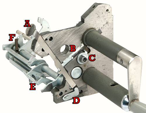
The back-transfer lifting mechanism is assembled in three grroves machined into the outer face of the right-hand end plate. The components are held in place by the outer cover plate.
The back-transfer button A is normally held raised by sliding latch B which engages with a notch in its stem. Latch B is held rearwards by a light torsion spring attached to the inner face of the outer right-hand cover plate.
When the rotor clearing handle at C is pulled forward, the tabbed washer pushes latch B forward via the small compression spring attached to its lower edge. The dimensions ae such that button A is not unlocked until the clearing handle reaches almost to the end of its forward travel.
When the clearing handle is fully forward, the button and stem can be pushed down against arm D, raising the lifting bail E on the lower cross-shaft. Arm D has a half-round hole which fits loosely over the half-round end of the cross-shaft, and usually falls out as the end plate is removed from the base.
Bail E raises the back-transfer gearset, which is locked into position by a latch in the carriage. The button A can then be released, and the lifting mechanism is reset by the arm and spring F at the far end of the cross-shaft.
This view also shows the upper cross-shaft, which carries the rotor rotational locking pawl at its left-hand end (behind A) and the non-return pawl (to the right of E).
 The counter register.
The Multo 113 counter register includes a tens-carry mechanism with a separate carry rotor, and an automatic reversing mechanism in the main body of the machine.
This front view of the register shows the numeral wheel detent levers mounted on the upper shaft, and the carry sensing levers on the lower shaft. The detent levers are held clockwise by the torsion springs between the anchor pins and the top supporting wire. The carry levers are held clockwise by a light coil spring attached to the same pin on the detent levers.
A set of carry latch levers and leaf springs are mounted in a rectangular cover under the carriage base. The latch levers rise through slots in the base and rest against the tips of the sensing levers.
This photo also shows the rather crude method of securing the clearing cam plate (at the end of the numeral wheel shaft) under the edge of the screw heads.
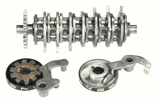 The counter carry components.
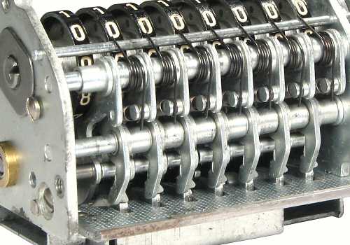
The carry rotor consists of 7 sections, each with a fixed locating disc and a spring-loaded movable disc. The rotor is mounted in a brass bearing directly below the numeral wheels. The pins on the movable discs are pushed sideways into engagement with the numeral wheel gears by camming surfaces on the carry levers. The principle is the same as in the accumulator, but the arrangement is rather different.
The detent lever (lower left) has a pinned extension which sits behind the carry lever for the next place. As the numeral wheel passes from 9 to 0, the long tooth next to the 7 pushes the lever further forward than normal, so that the pin pushes the downwards arm of the carry lever off the tip of the latch lever. The latch lever rises behind the carry lever to hold it forward.
The carry lever (lower right) has an inner arm which sits between the rim and the hub of the numeral wheel. As the tail of the lever moves forward, the camming surface (adjacent to the 9 in the photo) moves downward into the path of the pins on the carry rotor. The pin is pushed sideways as it passes and advances the next numeral wheel by one place.
Towards the end of the machine cycle, a camming surface on the fixed rotor discs momentarily releases the latch levers and allows the carry mechanism to reset. The inner arms of the carry levers rise close to the numeral wheel hubs and clear of the carry rotor. The lower arms sit back on the tips of the latch levers, ready for the next cycle.
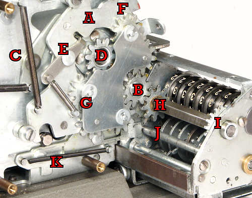 The counter reversing mechanism.
The Multo 113 has an effective and ingenious reversing mechanism which occupies a space of only about 12mm on the outer face of the left-hand end plate.
The reversing plate A pivots on the same post as the gear B. It is balanced and held in a "neutral" position by the vertical spring and detent lever at C.
A cam plate behind the gear D (on the end of the pinwheel rotor shaft) engages with the operating pawl E on the reversing plate. As the rotor begins to turn, it drags the pawl and the whole reversing plate assembly in the same direction. After a short distance the pawl is cammed outwards and into a fixed notch on the frame, where it is held by its spring. The rotor is then free to turn in either direction, but the reversing plate remains locked according to the direction of the initial turn.
When the reversing plate is in neutral, the two gears F and G are both partially engaged with the driving gear D. If the first turn is clockwise (in this view), gear G will move into full engagement and gear F will move clear. Gear D will drive through three identical intermediate gears in the lower section of the plate to turn output gear B in the same direction.
Had the first turn been anticlockwise, gear F would have been engaged and G disengaged. Gear D would drive through only two intermediate gears in the upper section to turn the output gear in the opposite direction.
Output gear B drives gear H in the carriage, which drives the carry rotor (visible below the dials) through the square shaft, gear I, and a small intermediate gear on the carriage end plate. Gear H is fixed in position by an arm which is attached to the left-hand end plate, behind the reversing plate. The square shaft slides through gear H as the carriage travels from end to end. The reversing plate must be removed and the locating arm disconnected before the carriage can be removed from the machine.
The reversing plate remains locked in position until the counter register is cleared. Bail J in the carriage is cammed rearward by the clearing mechanism, pushing the reversing reset slider K on the left-hand side plate. Slider K releases the operating pawl from its latch and returns the reversing plate to its neutral position via a V-notch cam and roller.