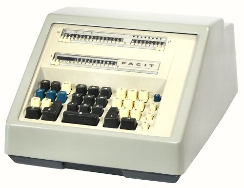
This page gives a brief technical description of the internal mechanism of the Facit CA2-16 fully-automatic pinwheel calculator.
The CA2-16 from 1962 (and the updated 10-07 from 1967) were among the last of the pinwheel calculators, and were the culmination of over 30 years of Facit's engineering development. Readers unfamiliar with the technology may find it helpful to review the following pages before proceeding:
The notes and photographs below were prepared during the overhaul of machine number 1508864 in June 2008. My thanks go to Mark Glusker in the USA who provided copies of the CA2-16 parts and service manuals (in German), and to Peter Tonelli, a former Facit technician from Tasmania, who provided the service frame and hand crank.
These notes are intended only as a general guide to the CA2-16 mechanism, and carry no guarantees of accuracy or completeness. Please do not dismantle a Facit in the expectation that these notes alone will get it back together!
I would welcome advice of any corrections, or suggestions for improvement.
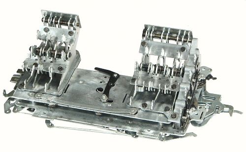
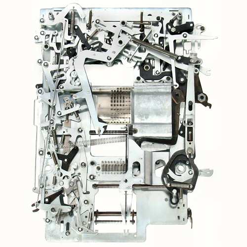
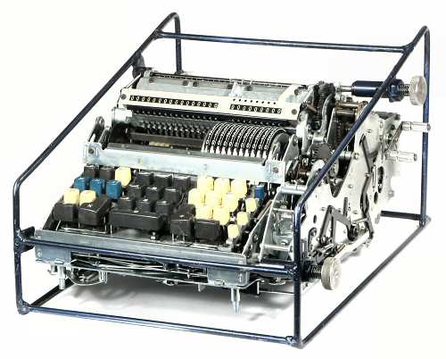 The CA2-16 mechanism
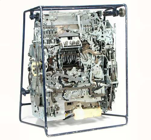
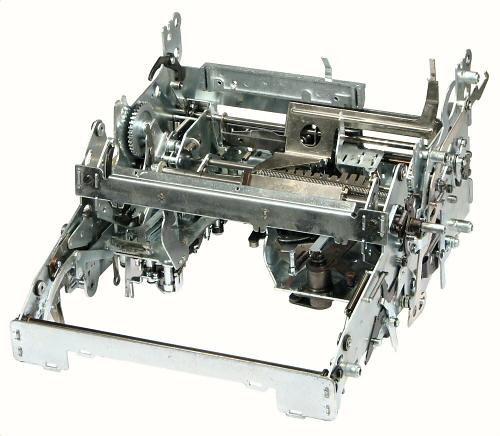
This view shows the CA2-16 mechanism mounted in the service frame. The frame keeps the mechanism clear of the workbench to avoid damage to protruding parts, while allowing easy access from all directions.
The keyboard is at the front of the machine, with the rotor towards the centre and the accumulator and counter registers behind. The main transmission is along the right-hand side, with the motor hidden at the rear. A hand crank is attached to the end of the first drive shaft at the rear.
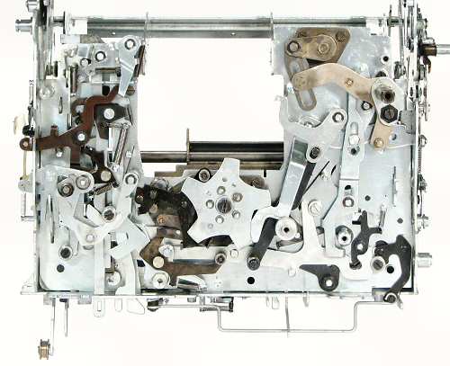
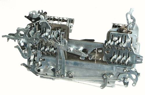
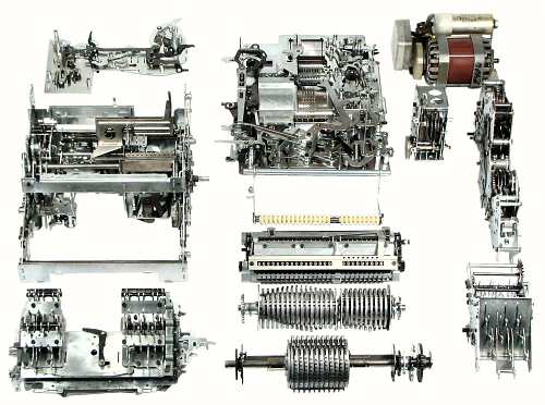 The mechanism disassembled.
The CA2-16 mechanism can be disassembled fairly easily into these 12 main modules.
At the centre left is the main body of the machine, with the function keyboard in front and the rear extension plate behind.
At the centre front is the setting rotor, followed by the carry rotors, the register assembly, the back-transfer assembly, and the large bottom plate at the rear.
At the front of the right-hand side is the numeric keyboard, followed by the left and right transmissions in the centre and the drive motor at the rear.
Each of these modules is described in more detail in the sections following.
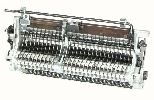
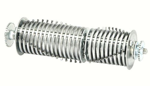
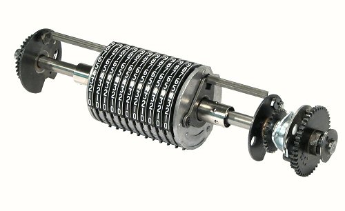 The setting rotor.
The CA2-16 rotor consists of 11 die-cast pin-wheels which are keyed and clamped to a central core. The setting rings have external gear teeth at the bottom and at the back to engage with the keyboard and the back-transfer mechanisms. The rotor body slides freely on a linear ball bearing on a 9mm shaft, which is mounted in removable bronze bearings in the main body of the machine.
The rotor is positioned laterally by a spring-loaded carriage and escapement mechanism. It is rotated in either direction by the rectangular steel bar between the two driving flanges, which are pinned to the shaft at either end. The bar has a ridge along the top which locks the setting rings, except for the one at the keyboard position. To clear the rotor, the lock is released and a bail pushes the rings back to zero.
The rotor shaft is driven from the main transmission by the large gear at the right-hand end, through a heavy spring-loaded brake and buffer assembly. The smaller gears drive the carry rotors.
 Main body - top.
The main body of the machine is generally similar to that of the hand-cranked CM2-16. It contains the rotor carriage and spring, the stepping escapement mechanism, the quotient coupling mechanism, the rotor return and clearing mechanisms, and parts of various control mechanisms.
 Main body - under.
The stepping of the rotor is controlled by a rotary escapement mechanism on the underside of the main body, under and around the five-pointed star wheel.
The spring-loaded rotor carriage is partly visible through the central cutout. It is connected to the escapement by a rack-and-pinion drive and a short vertical shaft through the base plate. As each digit is entered, the escapement allows the carriage to step one place to the left. The escapement can be released to allow the rotor to travel fully to the left for division setup, or to positions set by the tabulator keys for various back-transfer operations.
The heavy linkage at the upper right is part of the mechanism which returns the carriage, re-charges the spring, and clears the rotor.
The escapement and rotor return shafts are both carried in replaceable needle-roller bearings.
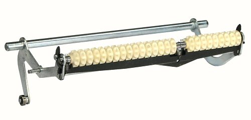
 The numeric keyboard.
The keyboard at the front of the machine actually consists of four separate modules - the numeric keyboard, two function keyboards, and a function key logic module.
The numeric keyboard has a power-assisted mechanism similar to that of an electric typewriter. The mechanism (bottom centre) is driven from the main motor by a spring belt on the left-hand side. The keystems are interlocked so that only one key can be pressed at a time.
The rear end of each key is in the form of a flat vertical plate with two shaped slots. The illustration shows the 8 key pressed, with its rear section raised. The rear slot engages with a cross-bar which lifts the toothed sector a known distance, and advances the rotor setting ring to the corresponding position. At the same time, an arm on the bottom of the sector sets the same number of pins in the multiplier pinbox in the base of the machine. The cross-bar is held firmly in a notch at the end of the stroke to ensure a positive setting with no overshoot.
The forward slot in the key engages another cross-bar which starts the motor and the power-assist mechanism as soon as the key begins to move. At the end of the stroke, the cross-bar releases the escapement. The spring draws the rotor to the left, and resets the keyboard as the escapement turns.
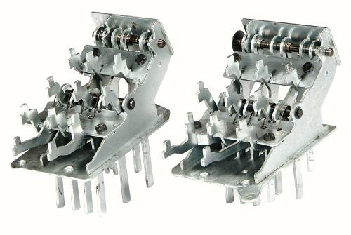 The function keyboards.
The function key modules on either side of the numeric keypad have ten keys each, with keystems of varying lengths extending downwards to engage with the mechanisms below. The keystems move rearwards as the keys are pressed, and have individual return springs.
 The function keyboard assembly.
The two function key modules are mounted on a base assembly consisting of two plates about 10mm apart. Between the modules and the top plate is another "swinging lever" interlock mechanism which prevents more than one key being operated at a time. The interlocks on the two modules are interconnected by the link across the top front. The L-shaped lever between the two modules blocks the numeric keyboard whenever a function key is active.
Between the top and bottom plates are three sliding aperture plates or "program plates". These are moved side to side by the keystems to select internal operations that are common to several keys. Other keystems connect individually to levers around the outside of the base assembly, while others extend right through the base to engage with mechanisms on the large bottom plate.
 The function keyboards - under.
On the underside of the lower plate is a set of tiny latching levers and springs which hold the keystems down while the function is in progress. The latches are released by another sliding plate which can be accessed at the left of the keyboard assembly (centre right in this underneath view).
The levers extending to the left engage with the +/- selection mechanism in the main transmission. Several of the individual linkages are visible along the lower edge.
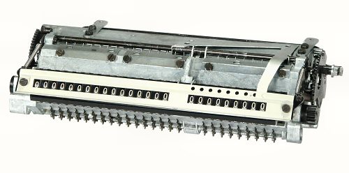 The register assembly.
The accumulator and counter registers (RIII and RII) are built into a substantial die-cast frame which sits at the top centre of the machine. The two registers are identical (apart from the number of digits), and both have full tens transmission. The setting rotor can engage with either register, allowing the "counter" register RII to be used for accumulation, storage, and back-transfer functions.
The pinwheels on the main rotor engage with the row of star wheels along the lower front of the register assembly. The star wheels drive a set of intermediate wheels which operate the detents and carry levers, and then drive the light plastic numeral wheels at the front.
The register clearing mechanism operates on the intermediate gear shaft via the cam-driven gear sectors on each side. The mechanism releases the detents before clearing to provide a quick and light operation.
 The register assembly - under.
The carry levers, detent levers, and springs are interleaved along the underside of the registers.
The last carry lever on the accumulator operates via the shaft across the top to control the automatic division, rather than just ringing the bell as on the manual machines.
Two short levers on the square shaft at the top left introduce a "fake" carry to advance the second register when it is being used as a counter. The counting is disabled when the register is used for storage or accumulation of totals.
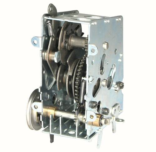
 The carry rotor.
The carry rotor is in two sections which are mounted on a common shaft in the main body of the machine, immediately below the register assembly. Each section has two symmetrical rows of staggered pins to provide ripple carries in positive or negative directions.
The accumulator section is driven from the left-hand end of the main rotor through an intermediate gear. The free gear at the right-hand end is driven through two intermediate gears, and hence rotates in the opposite direction. The control mechanism locks the counter carry drum to the accumulator drum in normal operation, or to the right-hand gear when counting backwards in division.
As the carry rotor returns to its home position, the camming surfaces between the discs reset the carry sensing levers in the register assembly above.
 The back-transfer assembly.
Prior to performing a back-transfer, the rotor is moved to the required position under the accumulator or counter register.
The back-transfer shaft is pivoted at the rear of the main body of the machine. It is raised by a cam and roller at the lower left to bring the gears into engagement with the star wheels along the lower front of the registers. The gears are held in alignment by the black locking bar until the mechanism is fully engaged. The gears rise into a recess in the rotor pinwheels, and lie between the setting rings.
When the shaft is in position, the main rotor is moved half a step to the right to slide the teeth on the back of the setting rings into engagement with the back-transfer gears. The register is then cleared. As the numeral wheels return to zero, the movement is transferred through the star wheels and back-transfer gears to advance the setting rings by the same amount.
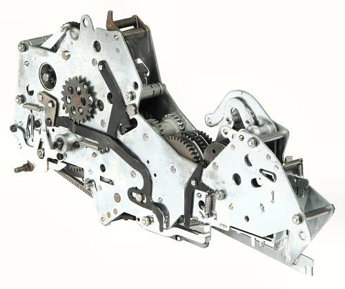 The main transmission.
The main transmission is mounted along the full length of the right-hand side of the machine. This view shows the inner side, which is normally hidden against the side of the main body.
The transmission receives power from the motor through the shaft at the upper rear, and drives the setting rotor through the second of the three large gears in the lowered section near the centre. The middle driving gear can be coupled to either of the contra-rotating outer gears for addition or subtraction.
The main transmission also contains the basic cycle control mechanism, the multiplier control and countback mechanisms, and the driving mechanisms for clearing the rotor and counter register.
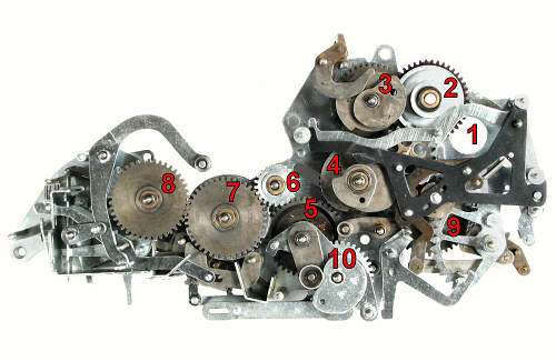 Main transmission - internal.
This view shows the main transmission with the outer cover plate removed. There are 10 sets of gears, six dog clutches of similar construction, and 4 sets of cams.
Gear 1 is the motor driving gear (removed).
Gear 2 is a fibre gear with a spring-loaded slipping clutch.
Gear 3 drives a clutch and cam which operates the RII clearing
mechanism via the curved arm at the top.
Gear 4 drives a clutch and multi-layer cam which controls the
multiplication process.
Gear 5 drives the reversing idler 6 and the innermost of the
contra-rotating gears 7. Gear 5 also has a clutch which drives a
second gear on the same shaft, which in turn drives Gear 10 and the
rotor clearing cam.
Gear 6 is the reversing idler, which drives the outer gear 7.
Gearset 7 consists of two identical contra-rotating gears, one on
each side of the rotor driving gear. An interlocking clutch mechanism
connects the rotor gear to one or other of the outer driving gears.
During multiplication and division cycles the clutches switch rapidly
from one direction to the other.
Gear 8 has a clutch and multi-layer cam which controls the basic
add/subtract cycles.
Gear 9 (mostly hidden) engages with Gear 4 and drives a cross-shaft
to the left-hand transmission.
Gears 1 to 8 form a continuous train which rotates (along with Gear 9) whenever the motor runs. Gear 10 only rotates during a rotor clearing cycle.
The linkages at the front of the transmission control the add/subtract cycles, while those at the rear control the multiplications. The count-back mechanism performs short-cut multiplication for digits 6 to 9.
 The left-hand transmission.
The left-hand transmission is a small module mounted at the left-hand rear of the machine. It connects through a removable drive shaft to the main transmission, and rotates whenever the motor runs.
The pulley on the outer end of the drive shaft drives the power-assist mechanism in the numeric keyboard. The upper clutch and cam drive the accumulator clearing mechanism. The two clutch and cam assemblies on the central shaft control the back-transfer and division setup operations.
 The rear extension plate.
The rear plate extends the machine body by about 100mm. It provides a mounting base for the left-hand transmission and some of the control linkages, and helps to support the large bottom plate. The long pillars at either side attach the rear of the mechanism to the bottom of the case.
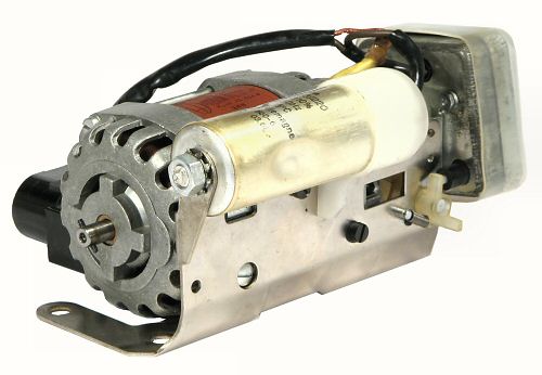 The motor and electricals.
The CA2-16 was available with either an AC/DC "universal" (brush-type) motor or a capacitor-run AC induction motor.
The AC motor and switchgear are assembled into a self-contained module which mounts on the rear of the main body of the machine. The mains input socket mounts on the lower section of the external case. The control box at the far end contains the motor switch, along with a filter choke and supression capacitor. The switch is operated by the small plastic lever at the lower right.
Warning: The mains input has only a two-pin socket with no provision for earthing. The motor assembly is well insulated from the body of the machine, but would not meet the modern standards for double insulation. Care needs to be taken when re-commissioning these machines, as any electrical faults could make the motor assembly alive.
The motors for the Australian 50Hz mains run at a nominal 1500RPM, and the gearing is set so that the setting rotor runs at 400RPM. Different pairs of driving gears were fitted for 60Hz mains and for the universal motors.
 Underside with bottom plate removed.
This view shows the underside of the machine prior to installing the large bottom plate. The keyboard assembly at the front (top) and the extension plate at the rear have merged seamlessly with the main body of the machine and the transmission at the right-hand side.
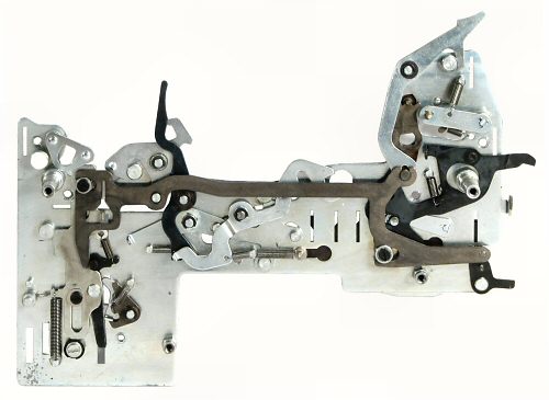
 The bottom plate.
The bottom plate covers the entire underside of the keyboard, main body, and rear extension plate. The levers extending from the right-hand side engage with the main transmission. Several keystems from the function keyboard engage with the linkages near the top, while other links from the main body connect along the left-hand edge. In spite of its complexity, the whole plate can be lifted off in a moment after removing just 5 screws and two nuts. Re-installing the plate requires a check to see that all of the interconnecting links and levers are properly engaged.
The pin carriage in the centre of the plate is used for multiplier or constant storage. Although described as a "memory", the pinbox can only be set from the keyboard, and can only be read back by the multiplier mechanism. (The accumulation and back-transfer functions on the counter register RII provide a versatile general-purpose storage or memory mechanism).
Numbers are set into the pinbox at the same time as they are entered into the main rotor, and are read back one digit at a time. The reading is done by a long "feeler" on a spring-loaded carriage at the bottom centre. The rotor, pinbox, and the feeler carriage have separate escapement and clearing mechanisms so that they can be controlled independently.
Apart from the pinbox mechanism, the bottom plate contains about 80 links and levers around the three sides. These provide most of the logic for controlling the rotor position and the direction of rotation during division, short-cut multiplication, and transfer operations. They also control the rotor and pinbox clearing functions, and operate the motor switch. The machine can not be operated with the bottom plate removed.
 The multiplier pinbox.
This view from the top front shows the pinbox and feeler mechanism on the upper side of the bottom plate.
To perform a multiplication, the pinbox is first cleared by pushing it to the right, which raises all of the pins. As the numeric keyboard raises its toothed sector to set the pinwheel, a lower arm sweeps forward above the pinbox and depresses the same number of pins. The pinbox escapement levers at the front right allow the box to step to the left.
When the X key is pressed, the pinbox position is locked by a lever engaging with the toothed rack at the lower left. The machine clears the rotor, but leaves the pinbox alone. When the second factor is entered into the rotor, the pinbox does not move. (The setting arm still sweeps across the pins in the current column, but the box never steps across to bring this column into an active position).
When the X= key is pressed, the feeler (top centre) springs forward to contact the first raised pin in the first column. This movement is transferred to a count-back wheel in the main transmission, which is returned towards zero as the machine cycles. On reaching zero, the feeler is withdrawn, the rotor and the feeler carriage step to the next position, and the process is repeated. The multiplication terminates when the feeler carriage reaches the last active column.
The count-back wheel senses the magnitude of the value transferred from the pinbox, and initiates "short-cut" multiplication for digits 6 to 9. If the value is (say) 8, the control mechanism will subtract twice rather than adding 8 times, and will perform an extra addition in the next (tens) column.