John Wolff's Web Museum
Anita Model 1011 Desk Calculator
Contents
|
|
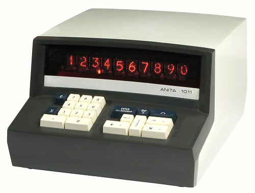
Anita 1000 Series, Model 1011, S/N M2971
Functions: ASMD, constant, percent, 1 memory
Technology: Discrete-component DTL, 7 IC chips
Display: 10 digits, Nixie tubes
Dimensions: 265W x 335D x 175H
Weight: 5.9kg
Manufactured: Bell Punch Company, England, January 1970
|
Overview
The Bell Punch Company of
England is generally credited with building the first production
electronic calculator - the ANITA - in 1962. The first ANITA was a
full-keyboard machine using vacuum tube technology, modelled on the
existing Sumlock
mechanical comptometers.
The "1000 Series" of solid-state 10-key machines was introduced
towards the end of 1969. The basic machine was a 10-digit
four-function desk calculator, with the different models in the
series offering different combinations of features - constants,
square roots, percentages, or a single memory register. The circuitry
was implemented primarily with discrete-component diode and transistor
logic, with a small number of MOS integrated circuits to provide the
storage registers. The circuit design and the keyboard interface used
the "postfix" or "reverse Polish" logic system.
In 1971 the functions of the 1000-series machines were redesigned
into less than a fifth of the volume by using the new MOS-LSI
integrated circuit technology. The 1000-LSI machines used only 5
custom-built IC chips and about 40 transistors to replace the
previous thousands of discrete components.
This page gives a brief overview of the construction, circuitry,
and operation of the discrete-component Anita Model 1011. A
similar page describes
the workings of the equivalent IC-based version, the Model 1011-LSI.
The descriptions are based primarily on my own observations and
interpretations, supplemented by reference to the 1011-LSI instruction
manual and some of the US patent documents. Corrections, comments, or
further information are welcome via the
Enquiry Form.
Construction
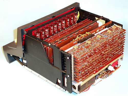 Internal view
The workings of the Anita 1000 Series are assembled between two
plastic side plates with moulded-in card guides. A horizontal
"base board" and a vertical backplane support the twenty circuit
boards. An extension at the front of the side plates supports the
metal frame of the keyboard, and the plastic front escutcheon. The
mains power supply, complete with 3-pin input connector and a
domestic push-button power switch, is mounted at the bottom rear
of the frame. The whole assembly slides into a substantial plastic
case which is moulded in a single piece.
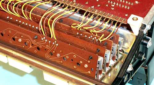 The keyboard mechanism
The Anita keyboard (seen here from underneath) is built up from
four long metal-framed switch modules which are mounted crossways
at the front of the machine. The modules have provision for ten
change-over switches, and are similar to those used on the earlier
full-keyboard Anitas. The four modules are connected to the base
board via individual flying leads and quick-connect lugs.
Circuitry
The logic circuitry of the Anita is built primarily from
discrete-component diode and transistor logic, with the storage
registers being provided by MOS integrated circuits.
The power supply produces +22V, +12V, and -12V for the logic
circuits, and +200V for the Nixie-style display tubes (Mullard
ZM1080s). Most of the rated 35VA is consumed by the display tubes
rather than by the electronics.
The operations are controlled by a master oscillator which
produces a complementary square-wave clock at 100kHz, along with a
number of synchronising and scanning signals.
The physical circuitry of the Anita 1011 is contained on a total
of 20 single-sided circuit boards, each 9" wide and 2, 3, or 4" high.
A detailed listing of the boards is
provided on a separate page. Three typical examples are shown below.
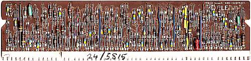 Diode logic boards
The ten 2-inch boards mounted horizontally at the rear of the card
cage consist primarily of discrete-component diode logic circuits.
This "Add/Subtract Logic" board has only 4 transistors, but over
100 diodes of several different types.
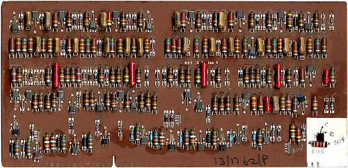 Transistor logic boards
This "Buffer" board is typical of the 3" and 4" boards mounted
vertically in the card cage. It contains discrete-component
diode-transistor logic, with 34 transistors and about 60 diodes.
This board has two additional components installed in a rather
crude manner in the white-painted area at the bottom right. The
components have pencilled numbers (TR37 and R106), suggesting that
they were an official field-service modification.
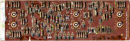 The Register board
The register board is one of four 3" boards mounted under the
display tube panel at the front of the machine. This board contains
six integrated circuits in 12-pin metal-can packages, mounted
upside-down in holes in the board. The white-painted area at the
left-hand end of the board contains six sets of (presumably)
assembler's or inspector's initials.
 Register board IC detail
The integrated circuits in the Anita were made by Marconi-Elliott
Electronics (ME). There are only two types, numbered MA09 and MA15.
The date codes show that they were made in weeks 45 and 48 (November)
of 1969.
This Register board has three pairs of chips, presumably to hold
the contents of the internal working register, the display register,
and the (optional) storage register. The small number of connections
to the chips (and to the board itself) suggests that the contents
are probably single-bit serial shift registers. There is another
MA09 chip on the Function Counter board.
Operation
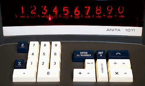
The calculator has a bright Nixie-tube display which always shows
the full ten digits, left-aligned with trailing zeros. The floating
decimal point uses separate neon indicator tubes between each of the
Nixies. There are two separate neons at the left of the display for
Minus and Store indicators.
The calculator operates according to the "reverse Polish" logic
system. For the four basic functions:
- key the first number (stored in the display register)
- press "Enter 1st Number" (copies the number
to an internal register)
- key the second number (if any)
- press a function key ASMD (performs the operation
on the two registers and displays the result).
Chain calculations can be continued in similar fashion.
The "C" (for Constant) key is a latching switch which copies the
display to the internal register and locks the contents for use in a
series of calculations. It is also useful with the Percent key.
For example, to calculate 50 + 5%:
- 50 C (copies 50 to internal register and locks)
- 5 % X (calculates 5% of 50, displays 2.5)
- + (adds the display to the retained 50, displays 52.5)
Strange results will follow if the C switch is accidentally left down
during the next calculation.
A third "Store" or memory register is accessed through the "EntS"
and "Store" keys. EntS copies the current display into the store
register, overwriting the previous contents. The Store key recalls
the contents of the register and lights the Store indicator until
one of the adjacent ASMD keys is pressed. The Add and Subtract keys
return their results to the store to provide an accumulation function,
while Multiply and Divide leave the store unchanged. For example:
- 2 Ent 1st 3 X Ent S
(calculates product 6, copies to store)
- 4 Ent 1st 5 X Store +
(calculates product 20, adds to store, displays 26)
- 2 Ent 1st Store X
(multiplies store by 2, displays 52, store remains at 26)
The blue key marked with the arch or semicircle rounds the display
to two figures after the decimal point.
Resources for further information
- The Bell Punch Company page
gives an overview of the company history and shows a selection of PLUS,
Sumlock, and Anita calculators.
- The Technical Section of this site
has descriptions of the workings of the "PLUS" mechanical calculator
and the IC-based Anita 1011-LSI electronic calculator.
- Nigel Tout from England has a very detailed history of the rise
and fall of the Bell Punch Company in his
Anita Calculators web site.
He has illustrations of many of their other models, both mechanical
and electronic, and tells the fascinating story of how a bus-ticket
company came to build the world's first electronic calculator.
Original text and images Copyright © John Wolff 2005-18.
Use at own risk; beware of errors; suggestions for improvement welcome.
Last Updated: 16 April 2018
Next:
Anita 1011-LSI
Back to:
Home
Calculating Machines
The Bell Punch Company
Tech Index