Contents
Contents |
|
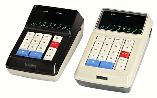
| Sharp EL-8 (1970) and EL-8M (1971). |
The Sharp QT-8D from 1969 is generally accepted as the world's first MOS-LSI electronic calculator. The QT-8D was a desktop machine measuring about 250x130x75mm, which was powered from the AC mains. In 1970 Sharp engineers replaced the mains power supply with a set of six C-size nickel-cadmium cells and a DC-to-DC inverter to produce the first battery-powered calculator, the QT-8B.
The experiment was successful, so Sharp set about refining and re-packaging the QT-8 technology to produce a compact battery-powered portable machine. In November 1970 they released the EL-8, which was advertised at the time as "the smallest electronic calculator in the world".
The EL-8M from April 1971 added a single memory register, a double-precision multiplication mode, and an extra row of memory keys in a longer but otherwise identical casing.
Both machines are basic 4-function 8-digit calculators, operating from an internal NiCad battery pack and a specialised external charger. They are built with typical early-70s technology, using multiple MOS-LSI integrated circuits, glass reed switches in the keyboard, and individual fluorescent display tubes.
This page describes the main features of their construction and operation. Unless noted otherwise, the description applies to both the EL-8 and the EL-8M.
External view
The EL-8 (left) is housed in a two-piece plastic casing which measures 102mm wide, 164mm deep, and 70mm high. The two parts of the casing clip together at the front, and are secured by a single screw at the rear. The calculator with its internal battery pack weighs 720g.
The EL-8M casing (right) has been lengthened by 20mm to accommodate the additional row of memory keys, but is otherwise identical.
The black-and-white colour scheme was available with a choice of either black or white on the top.
A re-packaged version of the EL-8 was also supplied to the Facit mechanical calculator company in Sweden, and was re-sold as the Facit model 1111 in competition with the Sharp-branded machines.
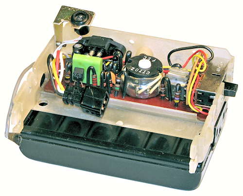
 Internal view
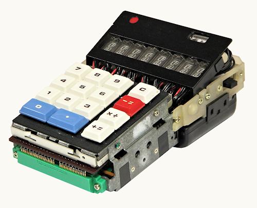
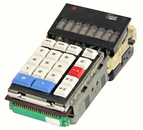
The front half of the EL-8 mechanism has a substantial pressed-metal frame to support the keyboard module and two circuit boards.
A full-length circuit board immediately below the keyboard carries the eight display tubes and their drivers, while a half-length board at the bottom front carries the four processor chips.
The inverter module is located at the rear of the machine, supported by the light-coloured plastic frame under the display tubes. The Ni-Cad battery pack is in the black clip-on casing at the bottom rear.
The internal mechanism is attached to the upper section of the casing by two pins at the rear of the inverter frame and two screws at the sides of the keyboard frame.
The EL-8M is constructed in the same manner, but with the keyboard and circuit boards lengthened by 20mm.
 The keyboard and card frame
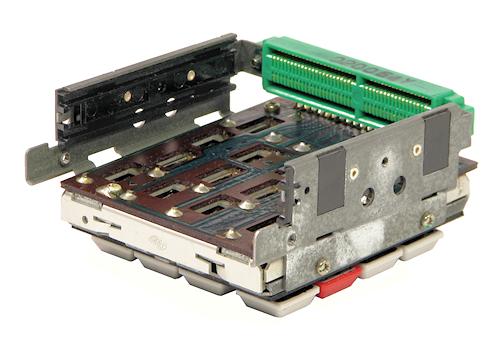
The ALPS keyboard module uses glass reed switches operated by moving magnets attached to the bottoms of the keystems.
A special two-slot edge connector for the two plug-in boards is soldered directly to the board carrying the reed switches. Plastic card guides are rivetted to the inside of the metal frame.
 The logic boards
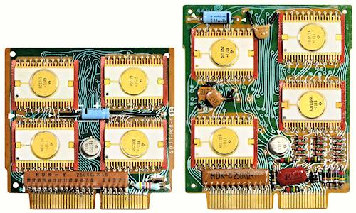
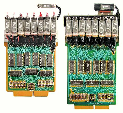
The EL-8 processor board (left) has a component area of 76 x 87mm and carries four Rockwell MOS-LSI chips in 42-pin ceramic flat packs. The part numbers are AU2271, NRD2256, DC2266, and AC2261, with date codes for weeks 42 and 43 (ie, October) of 1970. The board itself is date-stamped 45-12-9 on the back (ie, 9 December 1970).
The metal-can package is a CG1121 clock generator, producing a two-phase clock at about 45KHz (and a number of timing signals) from a 90KHz master oscillator.
The EL-8M logic board (right) is 20mm longer, with some additional keyboard logic at the bottom right. The EL-8M uses the same AU2271C, NRD2256, and CG1121 chips as the EL-8, with two new chips labelled DC1152 and ACM1156A. The date codes range from February to April of 1971. The board is date-stamped 26 May 1971.
 ELSI chip detail.
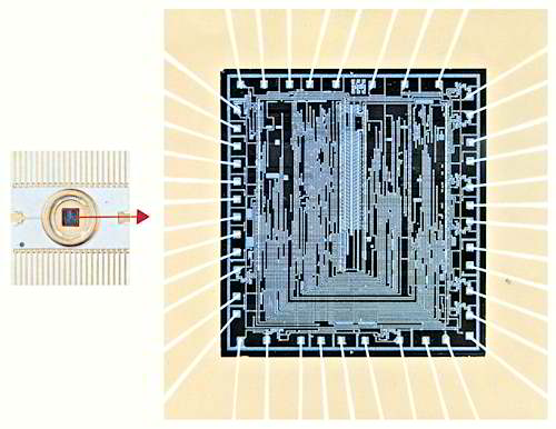
The chip technology used in the EL-8 was developed by Rockwell in America as part of their involvement in the Apollo space program. Sharp's advertising describes it as "extra large scale integration" (ELSI), with twice the performance of "ordinary" LSI and more than ten times that of standard (DTL) ICs.
This illustration (from an EL-8 sales brochure) shows the internal structure of an ELSI chip, which has the equivalent of almost 2000 components in an area of only 3 square millimeters.
Sharp used "ELSI-" in the names of many of their early calculators, but only "EL-" in the model number. The calculator described here was officially known as the "Compet ELSI-8", with a model number "EL-8".
 The display boards
The EL-8 display board (left) carries eight individual vacuum fluorescent display (VFD) tubes, Iseden "Itron" type DG10L. The tubes are 10mm diameter and 25mm high, with numerals 8mm high. They are attached to the board by flying leads from the base. A supporting bracket has been removed for the photograph.
At the top right of the display there is a special two-element VFD tube (Itron SP8A) which shows a horizontal bar for minus and a dot for error indication. This tube is mounted in a rubber block attached to the main tube support bracket.
Behind the display tubes is a 4-wire flying lead with an in-line plug-and-socket connection to the inverter module. The wires are colour-coded, but the connector is not polarised.
The lower section of the board carries nine MOS ICs in 16-pin packages to drive the display tubes. There are six Hitachi HD3120 and three HD3121, all with date codes of September and October 1970.
The EL-8M board (right) carries exactly the same components, but with a different track layout to suit the extended length. The chip date codes are all March 1971. The 8M board has a couple of minor improvements, including a more substantial support bracket for the tubes, and a polarised in-line connector for the power supply.
 Operator's display
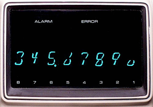
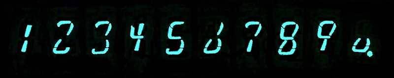
The "large-screen" display only has a single row of eight numerals, with the minus and error indicators at the top right and the power supply alarm indicator at the top left.
The DG10L numerals are formed from eight segments rather than the (now) usual seven, giving a script-like appearance with a distinctive half-height zero.
 Display tube detail
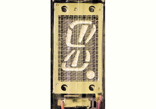
This close-up view shows the geometry and the electrode structure of the DG10L tube. The filament (the vertical white line) and the control grid (or mesh) are clearly visible. The numeral is only 8mm high, with the lines on the square grid about 0.7mm apart.
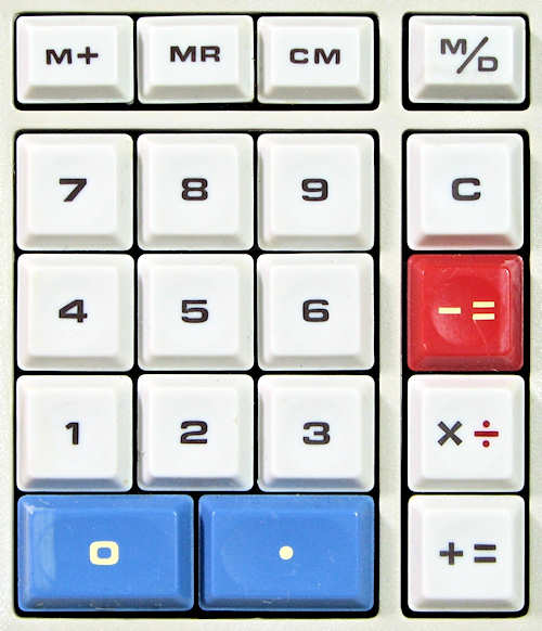 Keyboard operation
In common with many early calculators, the operation of the EL-8 and 8M has several "interesting" peculiarities.
There is no automatic power-on reset. When turning the calculator ON, it is necessary to press the "C" key twice to clear random numbers from the registers.
Addition and subtraction work normally, using "+/=" or "-/=" after each entry.
Multiplication and division are both marked on the same key - which one you get depends on which "equals" key you press afterwards! For multiplication, use +/=; for division, just match the red division sign with the red -/= key. Multiplications and divisions are completed in a maximum of 200mS. Successive calculations can not be "chained" together - it is necessary to use the "equals" key after every stage. For example, 2 x 3 x 4 +/= ignores the first operation and gives a result of 12 rather than 24.
The "C" key functions as both "Clear" and "Clear Entry", depending on whether any operations are pending. In the latter case it clears both the number and the operation, and restores the machine to the state at the previous result.
The decimal point floats within the available range, although the calculator attempts to preserve the number of decimal places entered if there is space available (eg 2.0 x 2.0 = 4.00). Results in division are always left-aligned with the maximum number of decimal places. There is no provision for roundoff.
The "Error" indicator lights for over-range or division by zero, and is cleared with the "C" key.
The EL-8M (illustrated) has an additional row of four memory keys at the top of the keyboard. The "M/D" key at the top right is a latching push-button which switches between memory functions and a "double-precision" multiplication mode as follows:
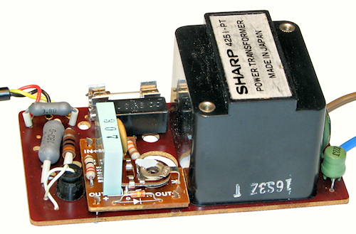
 The inverter module
The power supply arrangements in the EL-8 are almost as interesting as the calculator itself.
The logic circuits all operate from -25V DC, which is supplied from a small DC-to-DC inverter operating at 12.5kHz. The inverter is built on a single-sided board measuring 84x31mm, which carries the logo of SanKen Electric. The inverter board is mounted in a plastic frame in the rear section of the machine. The inverter frame is attached to the metal frame of the keyboard module, and also to the metal support bracket for the display tubes. The metalwork is grounded via the flying lead and solder lug at the far left. The battery pack is clipped on to the underside of the plastic frame, and is connected to the inverter via a plug and socket at the rear.
A specialised external AC power supply and battery charger connects to the custom 3-pin socket at the left-hand rear. The power switch on the right-hand side selects either AC or DC (ie, mains or battery) operation, with an OFF position in the centre. The inverter output connects to the display board through the flying lead and 4-wire connector at the front.
The small incandescent lamp at the left rear corner lights the "Alarm" indicator on the display.
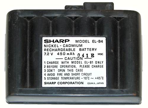 The battery pack EL-84.
The EL-84 battery pack consists of six AA-size nickel-cadmium cells in a plastic housing. The assembly clips on to the bottom of the inverter module, and connects via a polarised 2-pin plug and socket at the top.
The battery has a nominal capacity of 450mAh, and was rated to operate the calculator for three hours of continuous use. (Modern rechargeable AA cells have 4 or 5 times this capacity). Re-charging would take 15 hours with the calculator in use, or 3 hours with the power switch set to OFF.
The calculator will operate with battery voltages down to around 5V, with reduced display brightness. Current drain varies from 60mA at 5V (300mW) to around 120mA at 7.5V (900mW).
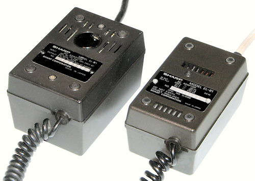 The external charger EL-81.
This view shows the undersides of two different versions of the external AC adaptor and NiCad charger.
Both units carry the same part number (EL-81) and have the same nameplate ratings. The larger unit has a multi-tapped transformer and a mains voltage selector, while the smaller version has a fixed 240V input and carries a type approval number for the Australian market. Other versions have a custom mains input connector instead of the fixed 2- or 3-wire cords. The EL-81 charger was also used with a several other early Sharp calculators.
The charger connects to the calculator via a short "curly cord" and a custom 3-pin plug. The input power rating is 5.5W, with outputs listed as 8.7V 150mA and 9.6V 230mA. There is in fact only one output, which is connected both directly and via an 8 ohm resistor to a complex switching arrangement in the AC/OFF/DC switch.
A separate EL-85 charger was available to power the calculator from a 12V DC automotive battery via the standard cigarette-lighter socket.
 EL-81 charger internals
This view shows the internals of the smaller EL-81 charger above. The larger unit has the same active components, but with a metal chassis to support the voltage selector and the larger multi-tapped transformer.
The charger has an L-C filter on the mains input at the right-hand side. On the output side there is a fuse, a bridge rectifier, three resistors, and a regulator module on a small daughter board. The 3-wire curly cord connects at the left rear corner. An incandescent indicator lamp at the front left corner lights in proportion to the battery charging current. Note that there are no reservoir capacitors in the charger unit, nor in the inverter itself.
The regulator output connects directly to the battery in the AC and OFF positions of the calculator power switch. In the AC position the inverter is fed from the regulator through a dropping resistor, while in the DC position it is fed directly from the battery. If the AC supply is connected while the switch is set to DC, it lights an "Alarm" lamp on the calculator display to warn the operator that the battery is not being charged.
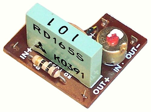 The regulator module
The daughter board carries a couple of resistors and an 8-pin "mystery" module labelled "RD165S" from Matsushita Electric (later National or Panasonic). The module functions as a three-terminal phase-controlled regulator.
The module takes the unfiltered output from the bridge rectifier, and produces a regulated output whose conduction angle varies with the load and the battery condition.
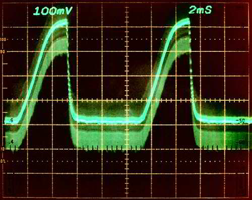 Battery current waveform
This CRO trace shows the battery current waveform with the calculator operating normally with a fully-charged battery.
The vertical scale is 100mA/div, with zero in the centre. The mains frequency is 50Hz. The "shadow" is due to high-frequency current pulses into the inverter.
Current flows in to the battery as the transformer output rises (towards 25V peak) on each half-cycle. The regulator monitors the instantaneous battery voltage and shuts off at a pre-set level of about 10V peak. Current then flows out of the battery to keep the inverter running until the next half-cycle.
The conduction angle varies from almost zero (calculator off, battery fully charged) to almost 180° with the battery fully discharged.
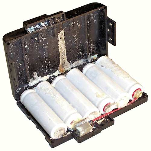 Replacement of the battery pack.
Although early NiCad batteries were advertised as "permanently sealed", the seals have rarely lasted 40 years. Because the EL-8 battery is inaccessible without opening the calculator body, it was generally not removed when the calculator was retired from service, leading to the results shown.
The nature of the phase-controlled regulator is such that the calculator simply will not operate from the charger if the battery is not present or not working. Nor will the charger produce any significant DC output unless it is connected to a battery or a substantial resistive load (about 20 ohms or 300mA). This has led some folk to discard the chargers as defective, and then to discard the battery pack and butcher the calculator to plug in an external DC supply.
Rather than making irreversible changes to rare hardware, or installing a new set of rechargeable cells for only an occasional demonstration, the following simple modification allows the calculator to be operated normally from the charger with the components and appearance preserved.
Drill out the rivet holding the battery case closed, remove and (responsibly) discard the old batteries and the connector, and clean the case. Remove the corroded battery plug and wiring from the inverter (noting polarity), and attend to any corrosion that may have travelled along the wires and onto the inverter board. Find an electrolytic capacitor of the same diameter as an AA battery, fit it into the case, and wire it directly to the battery connections on the inverter board (observing polarity). A value of 500μF at 12V is sufficient. The circuitry responds to the capacitor in much the same way as it would to a real battery, allowing the machine to be operated normally on the AC switch setting.