 Olympia Model CD-400, S/N 0209-14580
Functions: ASMD, K, percent, 1 memory
Technology: Bipolar DTL (Philco, 139 chips)
Display: 12 digit, Nixie tubes
Dimensions: 305W x 350D x 110H, weight 5.1kg
Manufactured: Made in Japan for Olympia, 1970
Olympia Model CD-400, S/N 0209-14580
Functions: ASMD, K, percent, 1 memory
Technology: Bipolar DTL (Philco, 139 chips)
Display: 12 digit, Nixie tubes
Dimensions: 305W x 350D x 110H, weight 5.1kg
Manufactured: Made in Japan for Olympia, 1970
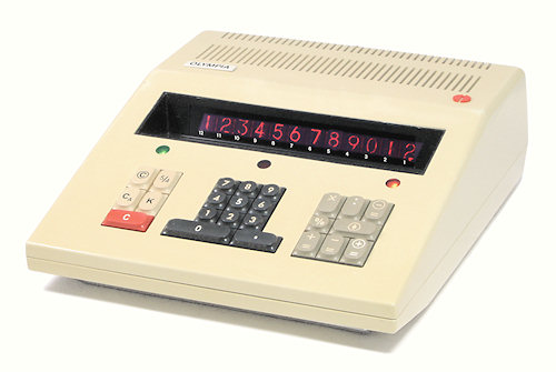
The Olympia organisation developed from the Union Typewriter Company, established by AEG in Berlin in 1903. Mechanical adding and calculating machines were introduced in the late 1940s. Olympia reached its peak in around 1970, but collapsed shortly afterwards as Japanese calculators and computer-based word processors put an end to its traditional office machine markets.
The Olympia CD-400 was made in Japan for Olympia in mid-1970. It is a basic four-function desk calculator with a 12-digit Nixie-tube display and one user-accessible memory. The logic circuitry uses 139 chips from an early Philco DTL family, with an acoustic delay line providing register and memory storage.
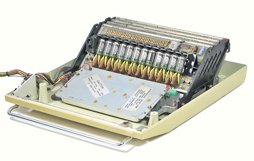 Internal view
The CD-400 is housed in a substantial plastic casing with a fold-out metal carrying handle at the front. There are rubber rollers at the rear to allow the machine to be moved easily on the desk.
The card cage contains four boards mounted at an angle of 45°, with the power supply at the rear. The metal-cased delay line module is mounted on rubber bushings in front of the display. The keyboard is mounted in the upper section of the case, and sits directly above the delay line.
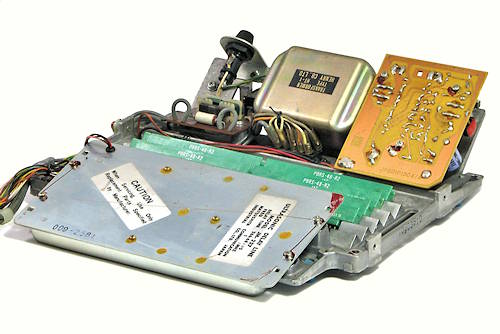 Chassis
This view shows the die-cast chassis of the machine with the cards and guides removed. The four rows of card sockets are mounted on a double-sided backplane in the bottom centre of the machine.
The power supply is built on a separate die-cast sub-frame which is attached to the rear of the main chassis. The power supply includes a mains voltage selector, line filter, and fuse, with a double-pole mains switch located under the front left corner of the case. The power supply produces regulated +5V for the logic circuits and +230V for the display tubes. Power consumption is rated at 18W.
The delay line module is from by Matsushita Electric Co. It has a transit time of 266.68 μS, sufficient to store about 250 bits of data at the specified 1MHz clock rate. The module contains its own drivers and sense amplifiers and produces logic-level outputs. It is hard-wired to the backplane with just four leads (5V, GND, IN, OUT).
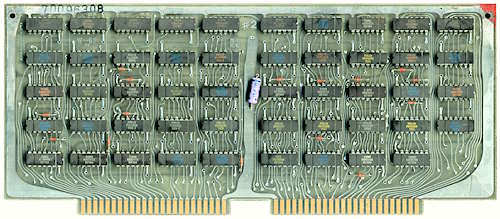
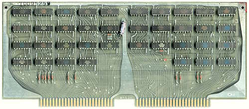
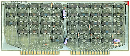 Logic boards
This view shows the first (rearmost) of the three logic boards. The double-sided boards have a component area of 255x105mm, and connect to the backplane via two 2x24-way edge connectors. Board 2 and Board 3 are similar. The logic boards have very few discrete components, apart from occassional bypass capacitors and supplementary diodes.
The logic chips are all from an early bipolar DTL series manufactured by Philco. There are only six different types, and each type is labelled in a different colour for easy identification. All of the date codes are from mid-1970.
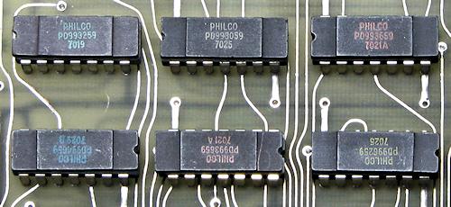 Chip detail
This view shows a close-up of some of the 139 logic chips. The part numbers and quantities are:
| 909359 | Brown | 35 |
| 993059 | White | 28 |
| 993259 | Green | 3 |
| 993659 | Orange | 20 |
| 994659 | Blue | 37 |
| 996259 | Yellow | 16 |
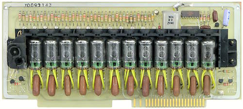 Display board
The display board carries 12 Matsushita CD72 Nixie-style display tubes. The tubes are 15mm diameter and 32mm high, mounted on 17mm centres. The numerals are 12mm high with a decimal point at the lower right. There are 7 IC chips mounted behind the tubes. The display tubes are multiplexed, with the anodes driven by discrete transistors and their associated R-C metworks. The resistors along the top of the board can provide some unpleasant surprises if contacted accidentaly. All the display tubes are dated August 1970.
The display board also carries a 3MHz crystal oscillator (at the upper right) which produces a 1MHz single-phase clock for the logic boards and the delay line.
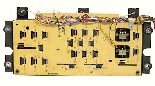 Keyboard assembly
The keyboard uses glass reed switches operated by moving magnets on the ends of the keystems. There are 22 reed switches, 2 latching pushbuttons, and three 6V indicator lamps. The assembly is built on a substantial pressed-metal frame which attaches to the underside of the top section of the case. A rigid plastic cover (removed for illustration) protects the reed switches when the keyboard is removed for servicing.
The keyboard is hard-wired to the backplane via a generous length of cable formed from individual wires. The keyboard is not multiplexed, so the cable carries only DC from contact closures to ground.
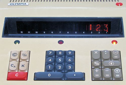
Although a relatively early machine, the operation of the CD-400 is quite conventional by modern standards.
There is a power switch under the front left-hand corner of the keyboard, and an orange power indicator light at the right. The machine resets automatically on power-up and shows a single zero at the right-hand side.
The function keypad on the right has the now-familiar +/=, -/=, Multiply, Divide, and Percent keys. The keys marked with a circle operate on the memory rather than the result register. A green lamp at the left shows when the memory is active. The diamond is the adding-machine symbol for Sub-Total, so the circle/diamond is equivalent to the modern Memory Recall. (The backplane connection for this key is actually marked MR).
The keypad on the left has two latching switches to select Constant and Round-off modes. C clears the input, CA clears all registers except memory, and circle/C clears the memory.
Overflow and error conditions blank the display and light the red indicator above the numeric keypad. The error is cleared with the CA key.