 The empty case.
Back about 1980 retired schoolteacher, clockmaker, and one-time bush band leader Mr Fank Pitt of Melbourne designed and built four small roll-playing crank organs of (about) 10, 20, 30 and 40 notes. With pencil and paper only he arranged a large collection of tunes for these organs, and cut the rolls for each by hand with a home-built punching machine. Three of these instruments are still in regular use by members of the Mechanical Music Society of Australia (MMSA) in Melbourne.
The smallest of the organs apparently did not meet Frank's expectations, and quietly disappeared from view. The mechanism was removed and discarded, but the case was carefully stored away in his workshop awaiting future inspiration. Frank was not a collector (he enjoyed working on clocks and musical instruments, but had no desire to own them), so the little organ case probably had special significance to justify its keeping.
Some 30 years later, as he reached his 90s, Frank "began to feel the increasing weight of the hand of Father Time", and decided to move to supported accommodation. In re-distributing his remaining posessions he presented me with the empty case of this long-lost instrument, with an invitation to "see if you can make something to go in this".
This page describes the process and the results.
The empty case.
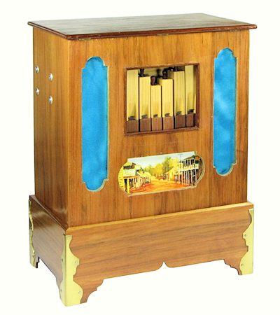
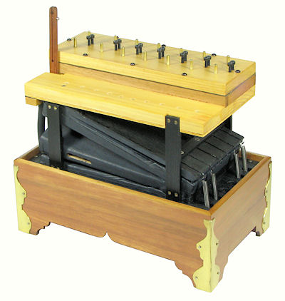
The organ case is very nicely built from veneered plywood, and finished with brass corners, blue satin in the side panels, and a "country town" painting in the centre panel. The design follows the normal crank organ arrangement, but on a very small scale. The internal space is divided into two sections by a base board near the top of the pedestal. The upper section, which accommodates most of the mechanism, has internal dimensions of only 280mm wide, 155mm deep, and 280mm high. The pedestal adds another 110mm for an overall height of 390mm.
The only item of mechanism remaining inside the case was a crankshaft with a winding handle and a single crank, mounted on two wooden brackets from the screws at the left-hand end.
 General arrangement.
The first decision to be made was whether the organ should play from a wooden barrel, cardboard books, paper rolls, or electronic microchips. Having previously built an automatic roll-punching machine for my organette rolls, a roll-playing mechanism seemed an obvious choice. While a "paper-as-valve" action (similar to the John Smith "Busker" organ) would be adequate for such a small instrument, I had doubts that the necessarily-large tracker bar and pressurised spoolbox could be accommodated in the tiny case. Also, as I wanted to use this project as a "try-out" for possibly building a larger organ at some later time, it seemed best to accept the complexity and build a full pneumatic valve action. The final design was based loosely on the plans which I had purchased some time ago for the Walter Höffle 20-note organ.
The next important question was the scale of the organ and the availability of music to suit. In working with the organettes I had acquired reasonable quantities of 14, 16, and 20-note rolls and tune sheets, so it seemed sensible to adopt one of these scales to take advantage of the existing musical arrangements. There seemed little prospect of fitting a mechanism for the 20-note scale into the space available, but after much experimenting it was found possible to accommodate sufficient pipes and valves to play the standard 14-note organette scale: C D E F G A A# B C D E F G A.
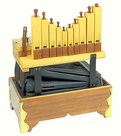
The general arrangement of the mechanism follows naturally from these basic decisions, and is quite conventional for a small roll-playing organ. The feeder and reservoir assembly is mounted on the base board at the top of the pedestal. The channel board is supported above the bellows. The ten smaller pipes are mounted directly onto the front of the channel board, with the windchest and valve box at the rear. The four largest pipes are mounted horizontally under the base board, and connected to the channel board by the rubber hoses at the left-hand end. The crankshaft and spoolbox (not shown) are mounted to the case, in the area behind the pipes.
 The pipes.
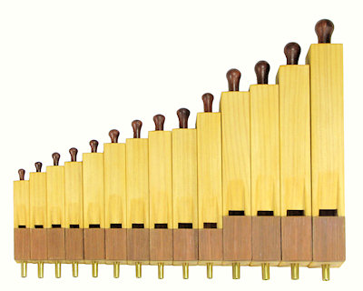
Having decided on the scale, the actual pitch of the organ was determined from the lengths available to accommodate the pipes. The maximum length available under the pedestal is about 215mm. A stopped pipe of this overall length would have a speaking length of about 145mm and a pitch of around A=440. This is a fortuitous figure, as it is exactly an octave above the usual pitch of the 14-note organette scale. (Or perhaps Frank had calculated it that way when he designed whatever was originally in the case).
The first pipe in the upper section would then be E=659, with a total length of 145mm. The channel board would need to be at least this distance below the top of the case. Allowing 20mm for the channel board itself would leave about 100mm for the bellows and reservoir assembly.
These figures were considered practical, so the scale and pipe dimensions were laid out in detail. The pipes were then constructed according to a set of notes that Frank had prepared and distributed some 30 years before, when speaking about his instruments at a Society meeting.
 The feeder and reservoir assembly.
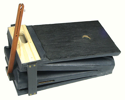
It was decided to retain the single-throw crankshaft and winding handle that were already fitted to the case, which then dictated the use of a single double-acting feeder. The crank throw was +/-20mm, which was in keeping with the 100mm height available. The feeder and reservoir were constructed in the conventional manner and covered with thin black garment leather with internal stiffeners. The unit occupies the whole of the available space (250x135x100mm approx).
In this double-acting construction, air is drawn in through the slots in the edges of the moving centre board, and is pumped through internal channels into the reservoir. The reservoir discharges through the slot at the top into the windchest above. The reservoir relief valve and the feeder flap valves are all internal.
In the absence of suitable leaf springs, the reservoir was fitted with long coil springs salvaged from a Comptometer calculating machine. The springs are shown in the next photo. The lower ends of the springs pass down through the base board and are attached near the bottom of the side wall, so that the length and tension stay relatively constant. It was found by experiment that each spring contributes about 1" WG (water gauge) pressure. Provision was made to fit up to six springs, but the organ was found to operate best with three.
 The channel board, windchest, and valve box.
Air from the bellows passes up through a slot in the channel board into the windchest and valve box at the top rear. The 14 valves are arranged in two rows, with the connecting nipples and adjustable bleed screws visible along the top. After passing through the valves, the air is directed to the upper and lower pipes through internal passages cut into the channel board.
The valve action was chosen to operate on the "exhaust" principle, so as to avoid the need for constructing a pressurised spoolbox. The design was based loosely on the plans which I had purchased for the Walter Höffle 20-note organ. The valve dimensions were reduced to fit the space available, but I suspect that they are still over-generous.
 The windchest and valve seats.
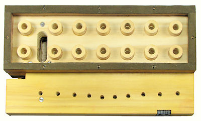
This view of the inside of the windchest shows the passage which brings air from the reservoir, and the 14 annular valve seats. The valve discs (next photo) sit on top of the valve seats and are held down by the air pressure inside the chest. When the valve lifts, air flows down through the valve seat and the channel board to the pipes.
 The valve board.
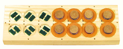
This view shows the underside of the valve board, partly assembled. The holes along the centre of the board and on the edges of the pouch wells provide the adjustable bleeds, while those in the centre of the wells are for the connecting nipples. The felt pads inside the pouch wells provide a buffer for the moving valve and prevent it blocking the inlet port.
 The valve assembly.
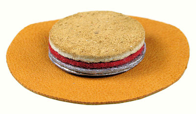
Each valve assembly consists of a disc of thin (0.008") pouch leather, two lead discs for gravity-assisted return, a felt disc, and a leather sealing disc. The pouch is 38mm diameter, and the other discs are 20mm.
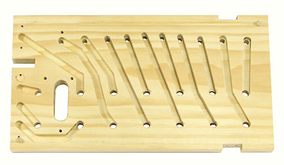 The channel board.
This view shows the air passages routed into the underside of the channel board. The four channels at the left supply the lower pipes via short rubber hoses near the end of the board, while the ten at the right supply the pipes along the front. A thin plywood cover is glued to the exposed surface to seal the channels. The feeder connecting rod passes through the slot in the left-hand edge.
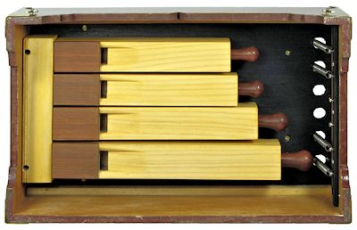 Underneath view.
This underneath view shows the four larger pipes installed in the lower section of the case. The mounting block at the left-hand end contains offset air channels to align with the rubber hoses above. (The hoses can not be evenly spaced because of the presence of the feeder connecting rod - see previous views).
Also visible in this view are the mounting arrangements for the lower ends of the reservoir springs.
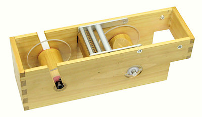 The spoolbox.
The spoolbox contains the removable supply spool on the left, the take-up spool on the right, and the "tracker bar" which reads the rolls in the centre. Each tracker bar hole connects to a corresponding nipple on the valve box. Two steel rollers hold the paper in firm contact with the bar, so as to resist the constant air pressure in the tracker holes below. The rollers are on a frame which swings over to the right to allow the rolls to be loaded and removed.
The take-up spool is driven from the main crank by a belt and pulleys, via a clutch that can be disengaged for rewinding. The driving pulleys (see next view) were calculated to give an initial roll speed of 3m/min at a nominal 90RPM cranking speed. This increases to about 5m/min at the end of the roll due to the increasing diameter on the take-up spool.
The roll is rewound on completion by disengaging the drive clutch and inserting a separate rewind crank into the hub of the supply spool.
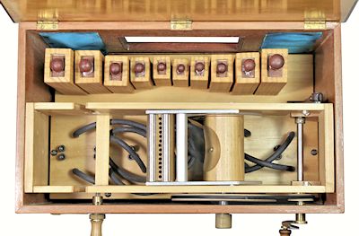 Spoolbox dimensions and mounting.
This top view of the organ shows the spoolbox mounted in the rear section of the case, directly above the valve box. The spoolbox is attached to the case at the left-hand end, and supported on the two crankshaft brackets at the right.
The width of the spoolbox is limited by the location of the crank for the feeder connecting rod (centre right), which is only 90mm from the back wall of the case. Subtracting suitable amounts for the belt drive and rewind clutch, the spoolbox sides, the roll flanges, and minimal end clearances, leaves a maximum of only 59mm available for the paper sheet with its 14 rows of holes. Using 3mm holes on 4mm centres requires an overall width of 55mm, which leaves a satisfactory 2mm margin on each side.
The tracker bar was constructed from a block of beech, with air channels drilled to two rows of offset brass nipples underneath. The mounting was arranged so that the spool box can be removed without disconnecting the tubing (ie, the tracker bar stays behind with the tubing still attached).
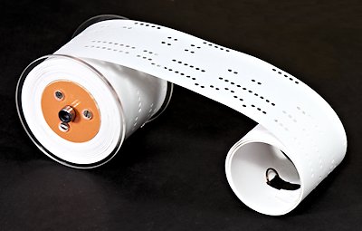 The music rolls.
The roll spools were constructed with wooden cores and clear acrylic ends. The usual 6mm socket-head screws were used for the end bearings and to receive the rewind crank. Each spool holds about 20m of paper and plays for about 5 minutes.
Twenty short tunes (from 30 seconds to two minutes duration) have been arranged and punched to suit the organ. Some have been transcribed directly from 7-3/4" tune sheets from the 14-note organettes, some have been arranged from 16-note Tanzbär accordion rolls, and some are original arrangements.
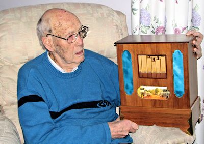 The project completed.
The organ was completed in August 2010. Frank was very pleased that I had taken up his challenge, and was delighted to see his "baby" instrument re-created after more than 30 years. As usual, he was more than helpful with advice on pipework, tuning, and suitable musical arrangements.
The project was finished just in time, as Frank died in March 2011, at age 92, after a short illness.
There are some audio recordings of the completed organ on the Sample music files page.