 A comparison of the production machine, as described in the preceding
sections, with Steiger's original patent descriptions shows the
extensive contributions made by Engineer Hans W. Egli in preparing
the design for commercial manufacture.
A comparison of the production machine, as described in the preceding
sections, with Steiger's original patent descriptions shows the
extensive contributions made by Engineer Hans W. Egli in preparing
the design for commercial manufacture.
A comparison of the production machine, as described in the preceding
sections, with Steiger's original patent descriptions shows the
extensive contributions made by Engineer Hans W. Egli in preparing
the design for commercial manufacture.
The illustrations below are extracts from US Patents 538710 and 558913. The full patents are available on-line from www.uspto.gov.
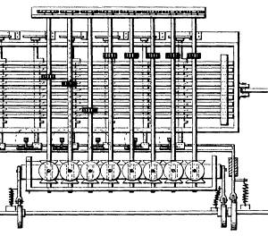 Steiger's 1892 patent sets out the basic principles of his
multiplying machine. The multiplication table, racks, cross-shafts,
sliding differentials, and the tens-carry mechanism are all clearly
described and illustrated. Three different constructions are shown to
illustrate some of the manufacturing possibilities. In one version the
multiplier body uses stepped discs rather than plates, assembled into
a drum or barrel which is rotated into alignment with the racks.
(Stepped or pinned barrels were established technology of the time,
and were used as control elements in applications ranging from
mechanical organs to Babbage's calculating engines).
In another version, Steiger shows stepped plates attached to the ends
of the racks, and actuated by a travelling comb which is lifted into
alignment by the multiplier lever. Steiger obviously had a thorough
understanding of the principles and the possibilities of his machine,
but was undecided as to a suitable way to build it.
Steiger's 1892 patent sets out the basic principles of his
multiplying machine. The multiplication table, racks, cross-shafts,
sliding differentials, and the tens-carry mechanism are all clearly
described and illustrated. Three different constructions are shown to
illustrate some of the manufacturing possibilities. In one version the
multiplier body uses stepped discs rather than plates, assembled into
a drum or barrel which is rotated into alignment with the racks.
(Stepped or pinned barrels were established technology of the time,
and were used as control elements in applications ranging from
mechanical organs to Babbage's calculating engines).
In another version, Steiger shows stepped plates attached to the ends
of the racks, and actuated by a travelling comb which is lifted into
alignment by the multiplier lever. Steiger obviously had a thorough
understanding of the principles and the possibilities of his machine,
but was undecided as to a suitable way to build it.
The 1895 application is concerned primarily with refining the details of one particular design which was to form the basis of the "Millionaire". Some of Steiger's details were used unchanged in the production machine, but a great many more were altered and improved by Hans W Egli as he prepared the design for commercial manufacture. Some of the more significant changes are described below.
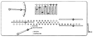 The most obvious external change was to the layout of the control
panel. The patent shows the Regulator and the add/subtract cams at
the lower left of the machine, with the winding handle mounted
externally at the right-hand end of the camshaft. These were moved
to the upper right of the panel to provide a more balanced and
functional layout, at the cost of an additional pair of bevelled
driving gears.
The most obvious external change was to the layout of the control
panel. The patent shows the Regulator and the add/subtract cams at
the lower left of the machine, with the winding handle mounted
externally at the right-hand end of the camshaft. These were moved
to the upper right of the panel to provide a more balanced and
functional layout, at the cost of an additional pair of bevelled
driving gears.
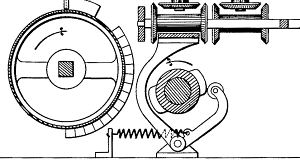
 The Steiger patent shows the moving carriage supported in mid-air
on two round shafts of perhaps 10mm diameter. The carry drum is
supported independently on its drive shaft, and is drawn along with
the carriage by a half-round yoke. The mechanism has a moving mass of
around 6kg, and must be held in close alignment with the differentials
and the carry drum. In the production machine the carriage and carry
drum are built as a single rigid unit, which is supported on steel
rollers running on replaceable steel rails.
The Steiger patent shows the moving carriage supported in mid-air
on two round shafts of perhaps 10mm diameter. The carry drum is
supported independently on its drive shaft, and is drawn along with
the carriage by a half-round yoke. The mechanism has a moving mass of
around 6kg, and must be held in close alignment with the differentials
and the carry drum. In the production machine the carriage and carry
drum are built as a single rigid unit, which is supported on steel
rollers running on replaceable steel rails.
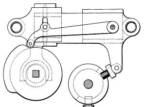
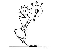
 All of the cams in the Steiger patent are shown in the conventional
form with spring-loaded followers, as in this drawing of the
add/subtract cam and the differential rocking shaft. This construction
has the disadvantage of requiring relatively strong springs to ensure
a positive return, with consequent increases in loadings and wear.
The production version replaced all of the plain cams with an enclosed
or slotted construction, ensuring a positive movement in both
directions without the use of springs.
All of the cams in the Steiger patent are shown in the conventional
form with spring-loaded followers, as in this drawing of the
add/subtract cam and the differential rocking shaft. This construction
has the disadvantage of requiring relatively strong springs to ensure
a positive return, with consequent increases in loadings and wear.
The production version replaced all of the plain cams with an enclosed
or slotted construction, ensuring a positive movement in both
directions without the use of springs.
 Similar changes were made to control over-run in the tens-carry
mechanism. The carry lever latching bar does not appear in the patent,
and there are no matching holes in the carry levers. The latching
mechanism was added to prevent mis-operation caused by the carry lever
moving more than one position when struck by the actuating arm
on the register shaft. Likewise, stop pins were added to the bottom
rail of the carry lever assembly to limit the travel at the second
stage, when the levers are struck by the cam blocks on the carry drum.
Similar changes were made to control over-run in the tens-carry
mechanism. The carry lever latching bar does not appear in the patent,
and there are no matching holes in the carry levers. The latching
mechanism was added to prevent mis-operation caused by the carry lever
moving more than one position when struck by the actuating arm
on the register shaft. Likewise, stop pins were added to the bottom
rail of the carry lever assembly to limit the travel at the second
stage, when the levers are struck by the cam blocks on the carry drum.