 The multiplier body.
The multiplier mechanism controls the movements of the racks in accordance with the multiplication table and the setting of the multiplier lever.
The multiplication table contains the products of single digits up to 9 x 9. It is divided into two halves to handle the tens and units of the results separately. The values in each table are represented mechanically in a "multiplier body" by pins or steps of varying length.
In operation, the multiplier body is positioned vertically and horizontally to bring the appropriate rows and columns into alignment with the left-hand ends of the racks. It is then pulled to the right by the drive mechanism, moving the racks according to the lengths of the selected pins.
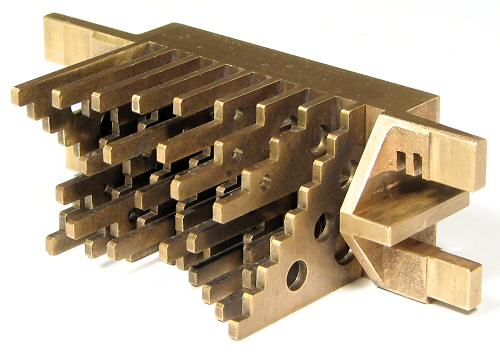
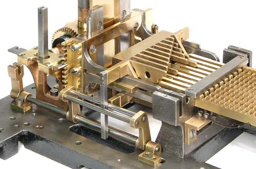
The multiplier body.
The base of the multiplier body is a block of brass measuring 35mm high, 58mm wide, and 13mm deep. Nine pairs of stepped plates are set vertically into the block to supply the tens and units values for each of the nine racks.
The plates are 2mm thick with 1.5mm spacers, for a centre distance of 3.5mm. The tens and units plates are arranged alternately, so that each set is on 7mm centres to align with the ends of the racks. Either set can be selected by sliding the block 3.5mm sideways. The inactive plates align with the spaces between the racks.
The plates are divided into 9 horizontal rows of 4mm each, corresponding to values 1 to 9 of the multiplier. The multiplier lever lifts the selected row into alignment with the ends of the racks. The length of the plate or pin at each grid position is the product of the rack number and the row number, for the tens and units separately. Each lengthwise step is 4mm, corresponding to a rack movement of exactly one tooth.
The illustration shows the multiplier body as seen from the rear of the machine. The nine "units" plates are clearly seen along the top of the block. The tens plates are mounted to the right of the units, but are not readily visible as the tens are all zero in the first row and column.
The "staircase" plate nearest the camera corresponds to the units table for rack 1. When the multiplier lever is set to 1, the single step at the top of the plate will align with the end of the rack. When the mutiplier body moves forward, nothing will happen until the last step, which will move the rack one tooth (1 x 1). Looking along the top row, it will be seen that rack 2 will move sooner and travel 2 places (2 x 1), rack 3 will move 3 places, and so on up to rack 9.
If the multiplier body is raised, each vertical step will cause rack 1 to move one additional place. Rack 2 will move 2 steps for each vertical step, but at step 5 its units plate returns to zero and the (hidden) tens plate is raised to step 1. The rest of the table is arranged in a similar fashion.
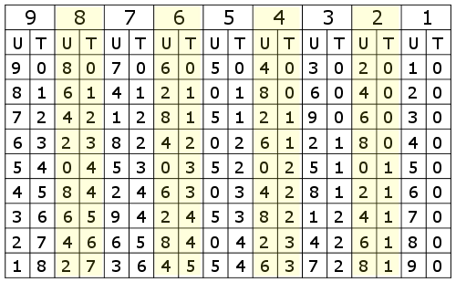 The multiplication table.
This chart shows the arrangement of the Units and Tens tables for each of the nine racks. The chart is drawn as if looking onto the pins of the multiplier body, in the same orientation as in the illustration above.
The numbers are the lengths of the pins at each location on the 9 x 18 grid.
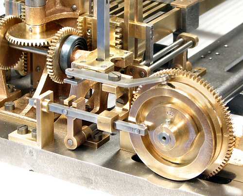
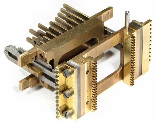 The multiplier body carrier.
The multiplier body is mounted in a rather complex carrier assembly which allows movement in three perpendicular directions.
Two slotted arms of 4mm steel support the horizontal lugs on the sides of the multiplier body, allowing it to travel forward to drive the racks. The lugs are wide enough to allow the multiplier to move 3.5mm sideways to select the tens or units tables. As the multiplier moves forward, the blade on top of the nearer arm engages with one of two notches in the upper brass lug to lock the tens or units selection.
The carrier is raised and lowered vertically by the two gear racks on the rear face. The serrated rack at the near end of the carrier provides a detent at 4mm intervals, while the notched rack at the far end locks the vertical position during the machine cycle. The pin on the top of the carrier provides a stop (against the underside of the top plate) if the multiplier lever is turned past 9. The bedplate provides a lower stop at the 0 position.
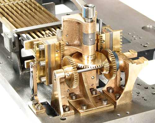 The lifting mechanism.
This view shows the multiplier lifting mechanism at the left-hand rear corner of the bedplate.
The multiplier carrier slides vertically on two steel guide plates at the edges of the vertical brass casting.
The lifting racks are driven symmetrically by a pair of gears of 37mm diameter on a short horizontal shaft. The shaft is driven through a pair of bevel gears from the multiplier lever. The lever has ten positions on an arc of about 60°, raising the multiplier through 9 steps of 4mm each.
A clock spring to the right of the lifting gears balances the 700g weight of the multiplier body and carrier, allowing it to be held in position by the detent arm and roller at the left-hand side. The setting is locked by a plate which slides between the rack teeth at the right-hand side during the machine cycle.
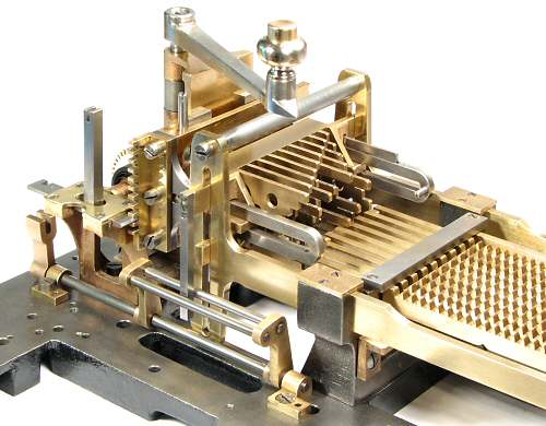
 The tens shift mechanism.
The tens or units tables are selected by sliding the multiplier body 3.5mm sideways, as previously described. Note how one set of plates aligns with the racks, while the other passes into the gaps between.
A length of 4mm square bar is attached to an extended arm at the top left of the multiplier body, and passes vertically down between two parallel rods mounted on a rocking frame. The frame is operated by a linkage from the left-hand end of the camshaft, so as to shift the multiplier body sideways in preparation for the tens and units cycles. As the multiplier is drawn forwards, its sideways position is locked by the horizontal blade on its rear support arm.
Also visible in this view are the detent springs under the racks (centre right), and the plate which locks the vertical position of the carrier (centre left). The arm extending above the locking plate operates a locking mechanism in the keyboard, via a linkage under the top cover plate.
 The tens shift cams.
The brass cam disc at the left-hand end of the camshaft is 57mm diameter and 10mm thick.
The cam groove cut into the face of the disc operates the tens-shift rocking frame via the horizontal sliding bar. The slot around the circumference of the disc operates the carrier locking plate via the angled lever at the top. The slotted cams provide positive movement in both directions without the additional loads that would be imposed by springs.
The clock spring that balances the weight of the carrier is clearly visible in this view.
 The rack drive mechanism.
The racks are pushed left-to-right by the multiplier body, which is drawn forward by two long brass rails from the crosshead at the right-hand end. The rails are machined from 4mm brass plate and are almost 400mm long. They are mounted in the rack support castings, and are secured with four screwed brass cover plates. The vertical arms at the end of the rails engage with the lugs on the sides of the multiplier carrier to move it forward and back.
The crosshead, rails, and multiplier body form a rigid frame which surrounds the racks. The frame travels 42mm, providing 9 steps of 4mm each and 6mm clearance. The clearance provides time for the camshaft to set up the functions required at the beginning of each stroke.
The racks are pushed back to their home position by the crosshead on the return stroke.
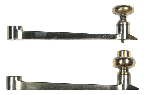 Manual and motorised differences.
The multiplier mechanism of the manually-operated machine differs slightly from the motorised version illustrated above.
The manual machine does not have the balance spring or detent mechanism, so its multiplier lever (top) must lift the full weight of the multiplier body and carrier (about 700g). A spring-loaded pin at the end of the lever drops into index holes at positions 0 to 9 on the top plate to hold the setting. The knob must be lifted to move the lever.
On the motorised machine, the multiplier lever is turned to the index positions and held by the balance spring and detent. The operator then presses the button in the centre of the multiplier knob, which presses a pin down through the index hole to operate the motor drive mechanism.
There are additional safety interlocks in the motor-driven machine, and other minor differences in the multiplier locking arrangements.