 The cross-shafts.
The cross-shafts pick up the movements of the appropriate racks, and transfer them through the differential reversing gears to the corresponding accumulator dials in the carriage.
There is one cross-shaft under each column of the setting mechanism, and one more on the left-hand side to drive the counter register.
The cross-shafts.
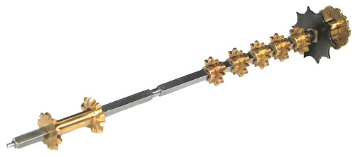
The accumulator cross-shafts are made from 4mm square-section steel, and are 208mm long.
The detent disc and star wheel are fixed to the rear of the shaft, while the pinions and differential gears are free to move.
The slide-set machines have only a single pinion, which is moved directly by the sliders to engage with one of the ten racks. The key-set machines have five pinions, which are normally positioned above the gaps between successive pairs of racks. Pressing a key will move one of the five pinions either forward or back, to engage with the rack on either side.
 The cross-shafts installed.
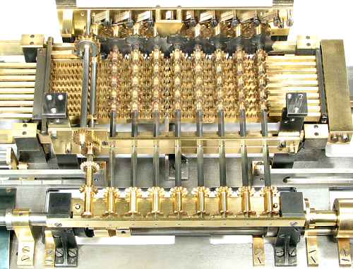
The cross-shafts are mounted above and at right-angles to the racks.
They are supported in plain bearings in three plates of 3mm brass, which are screwed and dowelled to six supporting pillars. The central plate is in two parts to form a split bearing.
The cross-shafts, setting mechanisms, and the carriage registers are spaced horizontally on 20mm centres.
The cross-shaft for the counter register (to the left of the eight accumulator cross-shafts) is described in the next section.
 The cross-shaft detents.
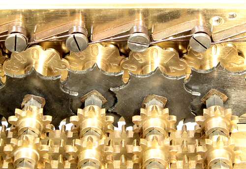
The cross-shaft detent arms and springs are mounted on a row of shouldered screws along the rear bearing plate.
The detent discs are the same pressing as the numeral wheels for the accumulator register, but are left as plain brass rather than finished. The black star wheels are part of an over-run protection mechanism which is described in a later section. The detent discs and star wheels are overlapped to fit within the 20mm column spacing.
Note the profile of the square hole through the pinions, where the flat faces have been relieved to reduce the contact area and friction.
 The differential gears.
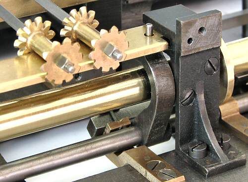
The front cross-shaft bearing plate has been removed for this view. It is normally attached to the vertical faces of the two short pillars near the central section of the camshaft. Two rearward-facing arms on these pillars support a horizontal brass plate which can slide a short distance fore and aft. The differentials sit astride this horizontal plate, with the register drive gears centred above and between them.
The differential plate is attached by two short vertical pins to the curved arms below. The arms are controlled from the camshaft via the horizontal rocking shaft at the bottom.
With the Regulator set for addition or multiplication, the rocking shaft will pull the differentials 4mm towards the front of the machine, so as to drive the register gears anti-clockwise from the rear face. The differentials move back to their "neutral" position while the racks are returning to their starting point.
For subtraction or division, the differentials move 4mm towards the rear of the machine to drive the register gears in the opposite direction from the front face.