 Regulator overview.
The Regulator conditions the machine for Addition, Multiplication, Division or Subtraction (AMDS). The accumulator registration is reversed between the outer pairs of functions (A-M and D-S), while the carriage shift mechanism is engaged for the inner pair (M-D). The four combinations are selected by a single member which slides along the camshaft. There are extensive interlocks to prevent mis-operation.
The camshaft also controls the carriage shift mechanism (described later), and the tens/units shift and keyboard locking (described previously).
Regulator overview.
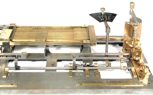
The vertical Regulator shaft is supported between the bedplate and the right rear top plate. The operating arm is just below the top plate, with only the knob above.
To set the Regulator, the knob is lifted and moved to detent positions adjacent to letters AMDS on the top plate. The words Addition, Multiplication, Division and Subtraction are marked on the sector plate attached to the arm, and appear through a window in the top plate when the Regulator is set correctly.
The Regulator can only be moved when the driving mechanism is in its home position.
 The Regulator linkages.
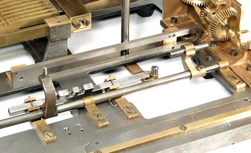
The Regulator shaft passes down through the bedplate and is attached to a horizontal brass arm. At the end of the arm is a roller which operates the camshaft mechanism. The camshaft controls the movement of the cross-shaft differentials via the T-shaped lever at the right-hand end of the rocking arm shaft.
A sliding interlock bar lies parallel to the rocking arm shaft and is also pinned to the end of the lower Regulator arm.
 The camshaft.
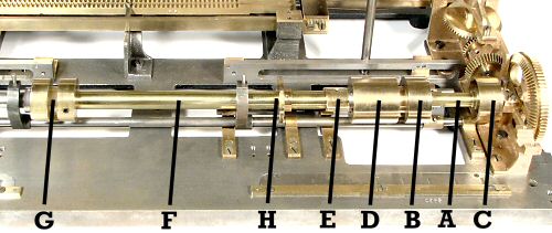
This annotated view shows the components on the right-hand end of the camshaft. The shaft itself is 12mm diameter and 635mm long. It is reduced to 8mm diameter where it is carried in plain bearings in the castings at either end. An intermediate plain bearing is mounted on a bracket to the left of the carriage shift cam.
The shaft carries two cam assemblies ABCD and EFGH in the right-hand section, and the tens/units cam (previously described) at its far left-hand end.
A is a sleeve which carries the addition and subtraction cams B and C respectively, and the hollow drum D. Sleeve A is keyed to the camshaft, but is free to travel lengthwise. It is positioned by the roller on the Regulator arm, which runs in the groove between cams B and D. The distance travelled between Addition and Subtraction is 29mm. Cams B, C, and D are 35mm diameter, and the assembly ABCD is 117mm long.
E is a driving dog which engages with a flange on the end of drum D, to drive through the long tubular sleeve F to the carriage shift cam G. H is a locking cam which engages with the interlock bar behind. Assembly EFGH is fixed lengthwise by pinned collars on the camshaft, but is free to rotate.
 The differential shaft actuator.
This view from the rear of the machine shows the mechanism that operates the differential rocking shaft.
The curved actuating arm is hinged from the bedplate between the add and subtract cams. It carries two offset rollers, which travel in the grooves of the deep slotted cams. The slotted cams provide a positive movement in both directions without the need for springs.
The profiles of the add and subtract cams are identical, but are 90° out of phase. The phase difference combines with the roller offset to provide the same "neutral" point for both cams. The cam lift provides 4mm movement either side of centre to position the differentials for addition and subtraction respectively.
 Addition.
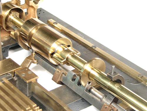
This view shows the camshaft and interlock bar positions with the Regulator set for Addition.
The Regulator arm has set the cam and drum assembly fully to the left (as seen in this view from the rear of the machine). The nearer roller on the rocking arm is fully engaged with the addition cam, and will move the differential shift arms towards the front of the machine at the approriate time.
The flanged drum is clear of the driving dog and will not operate the carriage shift mechanism. The locking cam is engaged with a lug on the interlock bar to ensure that the carriage shift mechanism does not move.
The driving dog performs another interlock function by preventing the drum assembly being moved to the right if the mechanism is away from its home position.
 Subtraction.
With the Regulator set to Subtract, the cam assembly is fully to the right. The rocking arm is fully engaged with the Subtract cam, and the differentials will move to the rear of the machine.
The carriage shift driving dog has disappeared inside the drum, but is again clear of the driving flange. The locking cam is engaged with the lug on the opposite end of the interlock bar.
 Division.
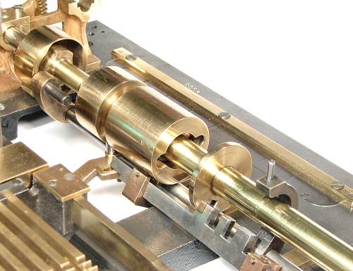
With the Regulator set to Division, the subtraction cam is engaged with the rocking shaft roller to only half its depth. The nearer roller is just clear of the addition cam.
The carriage shift driving dog is now engaged with the flanged drum, and the locking cam is aligned with a slot in the interlock bar. The whole assembly will turn as a unit as the camshaft rotates.
The machine cycle must then be completed before the locking cam will allow the interlock bar (and hence the Regulator) to be moved.
The setting for Multiplication similar, but using the addition cam.
 Camshaft drive key.
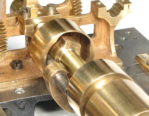
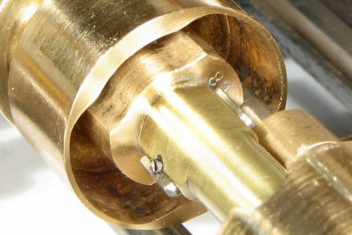
To transfer the drive to the sliding components, a 2.5mm slot is cut right through the 12mm camshaft. A tapered key measuring about 15 x 8 x 2mm is fitted through raised lands on the driven sleeve and secured with a small screw.