 The Figurematic keyboard.
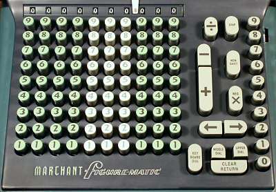
Ergonomics was rarely a strong point with mechanical calculators. Although the keyboard is the primary "user interface" to the machine, it was common for buttons, knobs, and levers (frequently un-labelled) to sprout from any available location, with little regard for the convenience (or accuracy) of the operator.
In contrast, the Marchant Figurematic has a very clean and simple keyboard layout, which successfully hides all of the complexities within. Apart from the numeric keys there are only 12 operator controls, which are arranged and labelled in a clear and logical fashion in a single panel along the right-hand side. (The training manuals suggest that the machine should be operated with the left hand).
In spite of the apparent simplicity of the keyboard, the Figurematic is a very capable machine which is a pleasure to use.
The Figurematic keyboard.
The numeric keys are colour-coded in thousands, with a sliding decimal point indicator above the check dial. The multiplier keys are arranged in a single column at the far right.
The control keys are arranged in two columns between the numeric keys and the multiplier. At the bottom are the clearing keys for the keyboard and the two carriage registers. The "Clear/Return" key clears both registers and returns the carriage to a (selectable) starting position.
Above the clearing keys are the right and left carriage shift keys, and above these on the left are the Plus and Minus keys. Plus and Minus only ever perform a single machine cycle, even if held down. To the right of these are two function keys which modify the action of the multiplier - "Non-Shift" supresses the automatic carriage shift between digits, and "Neg Mult" subtracts the product from a previous total in the main register.
At the top of the control columns are the "Division" key which clears the counter and commences the process of division, and a "Stop" key which clears most machine functions and terminates a division. Pressing the Stop key once requests the machine to stop in an orderly fashion at the end of the curent cycle, while pressing twice stops the division immediately. A small tab control to the right of the multiplier "8" key reverses the direction of the counter register if it is required to display complements.
During addition and subtraction, the keyboard is cleared automatically as soon as the setting phase has been completed. This allows the operator to start entering the next number while the add and restore phases are still in progress. This overlapping of operations (which computer folk now call "pipelining") allows a significant increase in speed for a skilled operator.
Notice that there is no "repeat" key to retain the keyboard setting for repeated addition. Although it is not obvious from the keyboard, the same effect can be obtained more quickly by pressing the Add key and a multiplier key simultaneously. The multiplier key performs the required number of additions, while the Add key supresses the carriage shift and enables clearing of the keyboard. A similar effect can be obtained by using the multiplier with the Non-Shift key. (See the Multiplier section for further details).
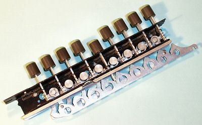 The keyboard modules.
The numeric keyboard is constructed from a series of independent single-column modules which are screwed to supporting bars at the upper and lower ends.
The nine identical key stems press downwards on the ramps on the sawtooth parallel bar, pushing it rearwards in proportion to the digit selected. There is a sliding lock plate to hold the key down, and a buffer strip under the top plate to reduce impact noise when the key is released.
To the right of the number keys is a different removable module supporting the Plus/Minus keys and the keyboard clearing key, while another at the far right supports the multiplier keys. The two columns of function keys are assembled as part of the control unit and are not easily removable.
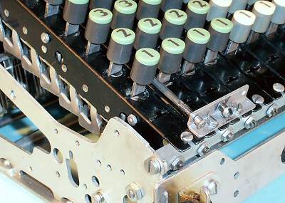 The keyboard modules installed.
Each module has a separate adjusting screw and lock nut to set its fore-and-aft position relative to the selector unit, so as to ensure that the check dial numerals are properly centred in their viewing windows. It may be necessary to bend the keystems slightly to adjust individual digits.
The "walking feet" on the left of the key modules are part of an elaborate interlocking system which ensures that only a single key can be pressed at once. The inertia of the bars contributes to the "feel" of the keyboard.
There are three small right-angle brackets across the front of the machine to secure the front of the keyboard escutcheon. The rear end of the escutcheon is clipped in place by the spring-loaded rods on the brackets at each side of the numeric columns.