 The division sensing levers.
In most mechanical calculators, division proceeds by repeated subtraction until an overdraft occurs. The mechanism then reverses and corrects the overdraft before shifting the carriage and re-starting the subtractions in the next column.
The Marchant calculator aims to improve the process of division by eliminating the wasted (and often noisy) machine cycles that are associated with overdraft and correction.
The division mechanism contains an analog magnitude comparator which compares the most significant digits of the keyboard with the current contents of the main register, in order to predict whether an overdraft is likely on the next cycle. In most cases the subtractions can be terminated before the overdraft actually occurs.
The comparator uses a set of sensing levers which can be raised to a height proportional to the keyboard column setting. The levers rise against the fingers which sense the contents of the main register via the positions of snail cams on the numeral wheels. If the keyboard setting is greater than the register contents, the sensing levers operate a trip mechanism which releases the roller latch and terminates the subtraction cycles. The machine then raises and shifts the carriage and re-starts the division in the next column. The process ends when the carriage reaches its leftmost position, or when the operator presses the Stop key.
This page describes the construction and principles of operation of the comparator and the division trip mechanism. The division sequencing functions and interlocks in the control unit will not be described in detail.
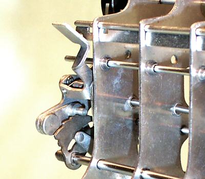
The division sensing levers.
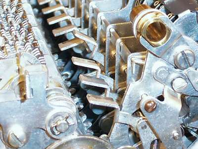
This view from the left-hand side shows the division sensing levers located in the gap between the selector and actuator units. Note that there are eleven sensing levers - ten are mounted in the selector columns, and one is mounted on a bracket dowelled to the outside of the left-hand frame plate.
During normal operations the sensing levers are disabled by forcing them downwards into the position shown. This keeps them well clear of the sensing finger guards so that the carriage can move freely. The levers are raised or enabled during division in order to read the contents of the main register via the sensing fingers and snail cams.
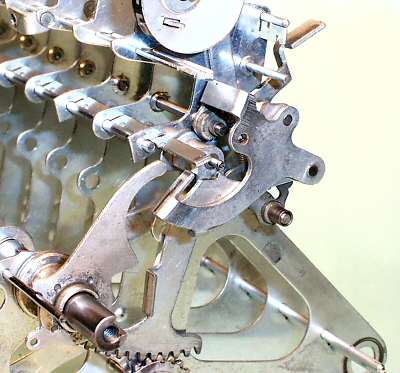
 The division trip components.
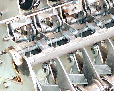
This view shows the components of the division trip mechanism in each column of the selector unit. Their functions are described in more detail in the sections following.
The sensing lever carrier is in the centre, with the lever itself at the centre left.
The keyboard input is obtained from the vertical sector arm in the selector unit (right), via the arm and pin on its right-hand side. The pin raises the small division quadrant (bottom centre), which in turn raises the carrier and sensing lever.
The sensing levers can be enabled or disabled by the double control arm assembly at the top left.
 The division quadrant.
This view from the right-hand side of the selector unit shows the quadrant mounted on its pivot shaft, just behind the keyboard attachment point on the selector arm. The sensing lever carrier rests on the stepped surface of the quadrant, immediately above the pivot.
With the keyboard at zero, the lower end of the selector arm is fully forward (to the left) and the quadrant slot is horizontal.
As the selector arm moves rearward from 0 to 9, the quadrant rises towards vertical. When the sensing lever assembly is enabled, the discrete steps on the upper surface of the quadrant will raise the sensing lever in proportion to the keyboard setting.
 The sensing lever and carrier.
This underneath view shows the details of the sensing lever and carrier. The whole assembly is only about 2" long.
The carrier A is attached to the selector plates by short pivot pins at B and C. Sensing lever D is attached to the carrier by the pivot pin E, and is spring-loaded upwards until the tab F is stopped by the carrier frame. The tripping point G on the front of the sensing lever interacts with the rearward fingers on the division gate (described below).
Pin H rests on the division quadrant and sets the height of the carrier and the sensing lever. Pin H is not mounted directly on the carrier, but is attached via balance lever I and pivot J. A light spring pulls the rear of the carrier downwards, so that when H rests on the quadrant, the forward end of lever I will be lifted up against the inside of flange L at the front of the carrier. The control arm acts on the outside of flange L to raise or lower the whole assembly.
The purpose of the notch at K will be described later. For the moment, assume that lever I remains hard against the flange L so that pin H remains fixed relative to the carrier.
 The sensing lever and quadrant.
This view from the left-hand rear shows the sensing lever in its raised or enabled position.
The keyboard column is set to 3. The short arm on the vertical selection lever has raised the quadrant through a corresponding distance, so that carrier support pin H is resting on the fourth step (counting from zero).
 The sensing lever and the control arm.
This view shows the same situation from the front right-hand side. The body of the carrier is more-or-less horizontal, with the flange L at about 45°. Lever I is visible just behind the flange, with notch K just below the selection lever pivot.
The sensing lever control arms are mounted on a keyed shaft towards the front of the selector unit, and are spring-loaded upwards. The shaft is operated by a cam and follower on the left-hand end of the setting line, and a latch mechanism on the right-hand end of the selector unit.
Each control arm assembly has two rearward-facing arms. The right-hand arm engages with flange L to enable or disable the carrier. The left-hand arm (hidden) provides an interlock with the next decade (described further below).
Note the 1/16" rod located just above the arm of the sensing lever, which is described in the next section.
 The sensing lever disabled.
The sensing levers are normally held disabled by rotating the control arm shaft clockwise through about 45°. The arm presses down on the flange L, rotating the sensing lever carrier almost to vertical.
As the front of the carrier is pushed downwards, the sensing lever pivot point E is lifted above the rod noted in the previous view. The rod toggles the sensing lever downwards via an over-centre action, leaving the inner end of the lever now pointing skywards. Pin H is lifted well clear of the quadrant, so that the selector arm can move freely for the next keyboard operation.
The control arm shaft is held in the disabled position by a latch at the right-hand end of the selector unit (not shown), and is released by the control unit only when required during division. The control arm shaft has a broad keyway which moves the arms together on the downward stroke, but allows them to move independently after the shaft returns.
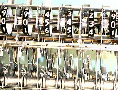 The control arm interlocks.
The control arms are interlocked in such a way that the sensing lever in a column can not rise unless all the keyboard columns to its left are set to zero.
This view from the top front shows the mechanism partially assembled with the keyboard dial set (arbitrarily) to 5430. The vertical selection sector arms for these digits have moved rearwards in proportion, as can be seen from the positions of the rectangular tabs on their lower sections. The columns to the left of the most significant digit are all at zero, with their selection arms fully forward.
When the control unit releases the control lever shaft, the double control arms will attempt to rise. If the column is at zero, the vertical selection arm will be fully forward, and the left-hand arm of the control lever assembly will be able to rise behind the rectangular tab. The right-hand arm will release the sensing lever carrier in the column to its right, which will rise and enable the sensing mechanism. If the column is not at zero, the tab on the selection arm will have moved rearward, and will block the curved flange on the side of the control arm. The control arms will be unable to rise, and the sensing lever will remain disabled.
The end result is that sensing only takes place in and to the left of the keyboard column containing the most significant digit of the divisor. The sensing lever in this column will rise proportional to the numeric value, those in the zero columns to the left will rise to the zero level, and those to the right will remain disabled. (The sensing levers are just visible at the top of the picture). The control arms are cascaded so that the process is not affected by intermediate zeros.
 The sensing levers enabled.
This view from the left-hand side shows typical positions of the sensing levers in the enabled state.
The lever in the left-most non-zero column has risen to a height proportional to the keyboard setting. The three levers to its left (closest) have risen only to the zero position, while those to the right remain disabled. (The leftmost carrier rises against a fixed stop at the zero position, as there is no corresponding keyboard setting mechanism).
The flattened shelves on the rear ends of the sensing levers rise against the fingers operated by the snail cams in the register dials. If the keyboard setting is less than the register contents, the levers will rise freely to their intended heights. If equal or greater, the register fingers will press down on the sensing levers, lifting the tripping points at the fronts.
 The division gate.
The division gate interacts with the tripping points to sense the result of the comparison, and trips the roller latch if the value remaining in the register is less than the keyboard setting.
The gate is a rigid toothed bar which extends the full width of the selector unit. It is normally hidden under the rear keyboard support bar (removed for clarity), just below the keyboard check dials. The gate is supported on two arms which are pivoted from the main frame plates, and is able to swing a short distance fore and aft. The rearward teeth on the bar engage with the tripping points at the forward ends of the division sensing levers. The teeth on the gate are graduated in length so that only one is active at a time, starting with the leftmost.
The gate is moved forward by a cam at the left-hand end of the setting line, and is normally held clear of the sensing levers by a latch at the right-hand side of the selector unit.
At the start of a division cycle, the control unit raises the sensing levers, and then allows the division gate to spring rearward. In the leftmost columns, the keyboard and register will generally both be at zero (ie, equal), the tripping points will be raised, and the division gate fingers will pass underneath. If the value in the active keyboard column exceeds the corresponding register column, this tripping point also will be raised, and the gate will continue rearward. The columns to the right are all disabled, so the gate continues fully rearward and trips the roller latch (via a linkage at the right-hand end) before the subtractions can commence.
If the value in the active keyboard column is less than that in the register, the tripping point will block the rearward movement of the gate and allow the subtractions to begin. As the register contents are reduced by subtraction, the register finger will start to press down on the sensing lever, raising the tripping point when the values become equal. The gate then continues rearward and terminates the cycle.
As the division progresses, remainders in the accumulator may be shifted to the left of the controlling order, requiring comparisons in two columns. Further columns may be active if the factors are not correctly aligned at the start. In all cases, the principle of operation is the same.
 The division gate trip point.
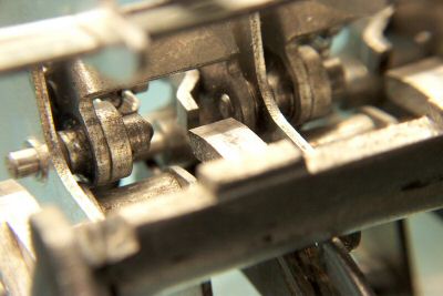
This close-up view shows how the horizontal and vertical edges of the division trip lever and the division gate extension intersect along the centreline of the carrier pivot, so that the tripping point will not be affected as the carrier is raised and lowered by rotation.
The carrier pivots can not be made as a continuous rod, but have to be broken into small sections which are fitted and retained individually.
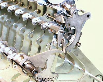
 The trip mechanism assembled.
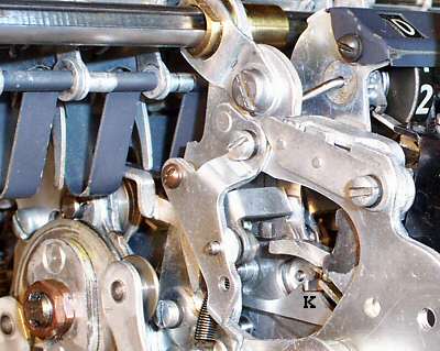
This view from the front left-hand side shows as much of the trip mechanism as is visible when the machine is assembled. A division is in progress, with the sensing levers raised but the division gate not yet released. The leftmost sensing lever has risen between the guards until stopped by the downwards finger on the carriage. (The fingers normally hang free until lifted by the sensing levers).
With the keyboard and the carriage both at zero, the trip point at the forward end of the sensing lever has been raised just above the tooth on the division gate. When the gate is released it will move rearward until it strikes the sensing lever in the active column, and when this trips the subtraction cycles will be terminated.
The description to this stage has been simplified by ignoring the complications of the Marchant carry mechanism.
Recall that the dials in the main register do not progress in whole-number steps, but contain incremental carries from the previous columns while an addition is in progress. If the register stands at (say) 25, the most significant dial (and its snail cam and sensing finger) will be at a position corresponding to 2.5, not integer 2. Likewise, the "tens" decade to the left of the most significant dial will contain 0.25, not zero. To make the comparison accurate, the positions of the keyboard sensing levers must also be modified (ie, raised further) to include one-tenth of the contents of the previous columns. This is achieved via notch K in the balance lever (see illustration above).
The small arm which sits above notch K extends leftwards from the hub of the vertical selection lever in the previous column. As the selection lever moves rearward from 0 to 9, the cross-arm presses downwards on notch K and the balance lever I. The support pin on lever I is resting on the division quadrant and can not move downwards, so the rear of the carrier has to rise. The lever lengths are set so as to add the necessary 10% increment.
The primary comparison thus takes place in the "tens" column to the left of the most significant keyboard digit, and always involves fractional keyboard values in the range 0 to 1. The steps on the division quadrant and the geometry of the carriage sensing fingers are arranged to give greater sensitivity at the lower end of the range.
It is still possible that the comparator's prediction may sometimes be incorrect, due to differences in the third place, or inaccuracies in the adjustment of the mechanism. The control unit logic will deal correctly with an overdraft if it does occur.
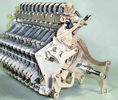 The division trip linkage.
The linkage at the right-hand side of the selector unit interacts with the control unit to latch and release the sensing lever control arms and the division gate at the appropriate times.
When the divsion gate is tripped by the sensing mechanism, the forked lever at the bottom right releases the roller latch in the control unit to terminate the subtraction cycles.
The notched lever at the top right is a safety interlock which engages with the carriage frame plates, to ensure that the carriage can not be moved while the sensing levers are raised.
Also visible in this view is the heavy bar which supports the rear end of the keyboard modules, mounted just below the check dials. The bar is attached to several of the selector frame plates, and to the main frame plates via the tabs at either side.