 Overview.
Overview.
The shift and clear mechanism is located in the right-hand rear corner of the machine. The operations are performed by cams and levers on the rear of the back plate, driven by gears and clutches on the front side. It's impossible to photograph both sides at once, so they will have to be taken separately.
 The rear cams.
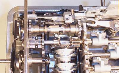
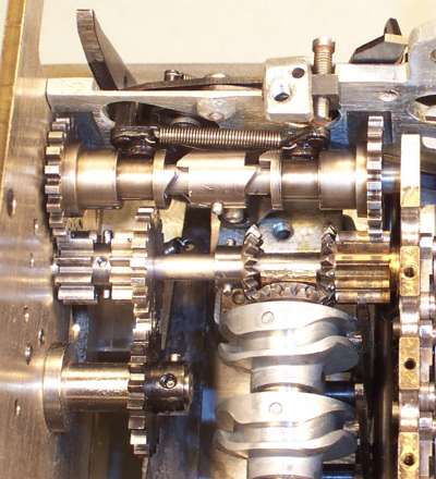
This view shows the cam and lever system in the top right corner of the rear plate.
The carriage shift is controlled by the circular disk to the upper left, via the two circular projections which engage with a corresponding rack at the bottom rear of the carriage. Half a turn of this disk will move the carriage one position in either direction. The outermost teeth on the carriage rack are spring-loaded, so that the shift mechanism can cycle without causing damage at either end of its travel. The shifter disk is held firmly in its rest position by the locking bar, which is raised against the projections by the front (ie, closest) cam on the central shaft.
The vertical lever to the right of the shifter disk is pushed sideways as soon as the disk commences to rotate. The V-shaped notch at the bottom of this lever engages with a pin which is visible through the hole in the rear plate. This pin connects to an arm on the shaft which positions the differentials. The V notch forces the differentials into the neutral position while the carriage shift is in progress.
The rack at the top of the rear plate measures the carriage position, and communicates this to the multiplier unit via the two large gears.
The carriage clearing mechanism is driven by the second cam on the central shaft. This pushes leftwards on the circular follower, then via the horizontal link to the vertical arm at the far left. This tip of this arm travels about 20mm leftwards to operate the clearing racks for the accumulator and counter registers (Registers I and II) in the carriage.
The horizontal link extending to the bottom right drives a further mechanism to clear the multiplier register (Register V) at the front of the machine, and to operate some automatic functions on the left-hand side.
The rearward extension on the central cam shaft drives the camshaft mechanism in the carriage, via a dog clutch and bevel gears.
To gain an appreciation of Madas precision, consider that there are two clearing racks in the carriage (for the counter and accumulator registers). These racks are each 2mm wide, and are located side-by-side with no gap between. The clearing arm is 3mm wide, and can be moved fore-and-aft to engage with either rack, or neither, or both together. Clearance commands are generated (manually or automatically) by the levers in the centre of the left-hand side. Although there are five intermediate levers with a total length of about 450mm, the machine still manages to position the clearing arm to within a fraction of a millimetre.
 The gears and clutches.
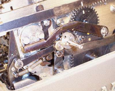
Apart from the motor drive, these are the only "transmission" gears in the Madas. In the centre is the extended shaft from the first stepped drum, which carries the incoming drive from the mainshaft. The upper shaft drives the carriage shift via the central dog clutches, and the lower shaft drives the cam shaft on the back panel. (The carriage clearing arm is prominent in the top left corner).
The rear-panel cam shaft is driven 1:1 by the gears pinned to the left-hand end of the central shaft.
The slotted carry camshaft is driven by the bevel gear in the centre of the input shaft. The brass gear at the right-hand end is not pinned to the drive shaft, but is driven by the carry camshaft gear in differential fashion, and hence rotates in the opposite direction to its shaft.
The outer halves of the dog clutches on the carriage shift shaft are geared 1:2 to these contra-rotating gears on the central shaft, so that the ouput shaft will make the required half-a-turn in either direction during a full mainshaft cycle. The clutches can be slid inwards into engagement via the spring-loaded levers. The levers are tripped by latches on the outside of the side plate, and are reset by a cam on the mainshaft at the end of the cycle.
The alignment of all these gears is critical. The rotation of the carry camshaft must match the timing of the locking pawls on the stepped drum shafts. The rotation of the carriage shifter (in both directions) must correspond exactly with the rise and fall of the locking bar.
This machine had been assembled incorrectly by a previous repairer, causing one of the projections on the shifter disk to foul on the locking bar during the rotation. This has resulted in considerable wear on the disk and the drive gear. When properly assembled, the locking bar is highest at the starting position, and is just clear of the shifter disk throughout the complete cycle. The gears have either 10 or 20 teeth, so errors will be in multiples of 18 degrees and should be fairly obvious (as in this photo, which shows execessive clearance on the right-hand clutch).