 The carry mechanism components.
The tens transmission or carry mechanism connects each column to its neighbour on the left, so as to advance the higher column by one place for each full revolution of the lower. One revolution corresponds to ten counts on a decimal column, but on a Sterling machine there are columns with cycles of 2, 4, 10, and 12 counts.
At its most basic level, the Comptometer carry mechanism consists of two main sections:
The carry mechanism also has a number of auxiliary components and functions, including:
The carry mechanism components.
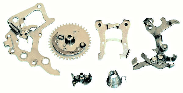
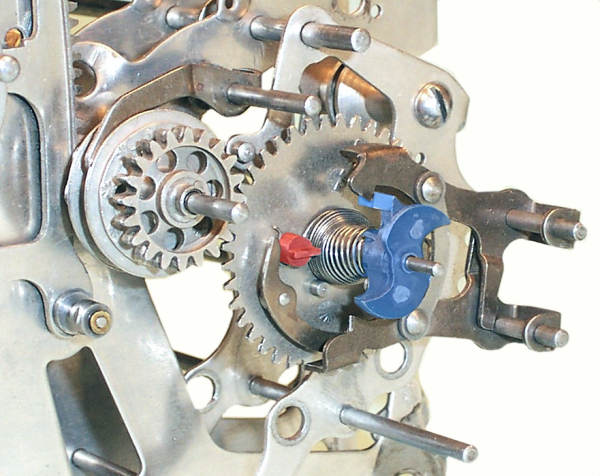
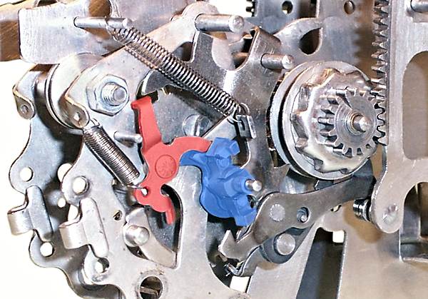
This view shows the major components of the carry mechanism. In the centre are the carry gear with its C-shaped cam, and the pair of escapement detent levers. Below these are the escapement wheel and the carry spring. The carry gear winds the spring, and controls the release of the escapement wheel via the cam and the detent levers.
The escapement components are mounted on a separate sub-frame (the "rock frame") which hangs from the intermediate gear shaft at the front of the machine. One of the rock frame side plates is shown on the left. A small 3-armed lever (the "carry lever locking dog") is riveted to the the rock frame plate.
On the right is the carry lever or "carrying bell crank", which transfers the carry into the next column when the escapement wheel is released.
Each of these components is described in more detail in the sections following.
 The carry gear and escapement wheel.
The large carry gear of 40 teeth is driven by the accumulator gear (20 teeth), and drives the numeral wheel (20 teeth) via the intermediate gear. The carry gear thus rotates exactly half a turn for each full cycle of the numeral wheel. The carry gear rotates anti-clockwise in this view.
The large "C"-shaped bar attached to the carry gear functions as a cam to operate the escapement detent levers. The cam is assisted by a roller at its leading edge (bottom).
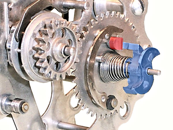
The escapement "wheel" (blue) sits next to the carry gear on the same 1/16" wire. It is only about 1/2" across, but consists of five separate components. The largest is the central hub, with two opposing lugs which engage with the detent levers and interlocks. One of the lugs (top) has an extended horizontal arm which engages with a flattened stop pin (red) on the carry gear. On the outside of the hub are two "S"-shaped cams. The outer cam operates the carry lever, while the inner (hidden) drives the carry lever locking dog (described later). The body and two cams are held tightly together by two rivets.
The spiral carry spring in a Model J decimal column usually consists of 13 turns of 0.013" wire, with a free length of about 1/2". The larger end is wrapped around the base of the stop pin (red) on the carry gear, and the smaller end fits into a slot in the hub of the escapement wheel. The spring is given a substantial pre-load by winding the escapement wheel one full turn clockwise and tucking the long arm behind the stop pin.
Comptometer springs were revised frequently to refine the "touch" of the keys. Model H used 1.5 turns preload, and some escapement wheels from the transition period (including the one illustrated) had two anchor slots to allow for use on either model. Non-decimal columns have different spring combinations.
 The carry cam and detents.
The two escapement detent levers are pivoted on 0.088" wires at the front of the rock frame. The levers can only move a small distance vertically, with the "tails" on their hubs acting as stops against the opposite wire.
The two levers are connected by a short riveted link in the Model J, but earlier models used a spring.
The cam on the carry gear runs inside the flattened horizontal section at the end of the detent levers, raising and lowering the detents alternately on each half turn.
Note the forward and rearward-facing stop teeth on the inner surfaces of the detent levers, which will engage with the lugs on the escapement wheel.
 The escapement at zero.
In this view, the roller on the carry gear cam has just entered the lower detent lever and pushed it downwards. The connecting link pulls downwards on the upper lever, bringing the hooked detent tooth downwards and blocking the movement of the top lug on the escapement wheel.
The numeral wheel is set to display zero when the carry gear stands (approximately) in this position.
The zero setting is described further in the Clearing section.
 Winding the carry spring.
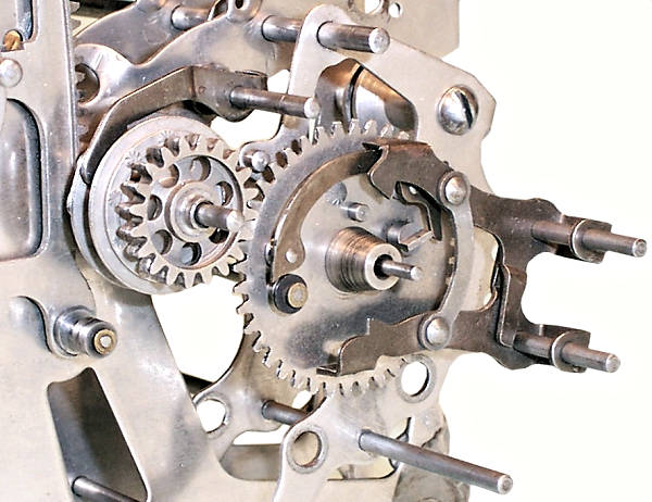
As the accumulator advances, the carry gear rotates anti-clockwise, but the escapement wheel is held fast by the upper detent lever. The relative motion winds up the tension in the carry spring. The illustration shows the carry gear in mid-cycle after 5 counts.
The increased tension is held between the detent lever (which restrains the escapement wheel) and the backstop (which restrains the pins of the lantern wheel).
 The escapement released.
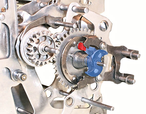
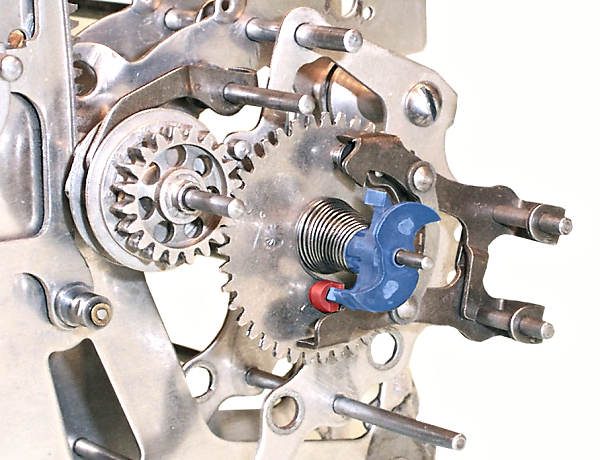
As the numeral wheel passes from 9 to 0, the roller at the front of the carry cam lifts the upper detent lever clear of the top lug on the escapement wheel. The wheel is driven forward (anti-clockwise) by the carry spring until its long arm again strikes the stop pin, half a turn around from its original position (note the short arm is now at the top).
At the same time, the connecting link pulls the lower detent lever upwards, so that its rearward-facing tooth will block the movement of the escapement wheel when the carry gear moves on.
The process is repeated on the next cycle. The end result is that the carry gear advances along with the numerals, and the escapement wheel follows half-a-turn at a time whenever the numeral wheel passes from 9 to 0.
Note that the short arm on the escapement wheel (uppermost in this view) takes no part in generating the half-turn motion. It belongs to the duplex mechanism, described later.
 The carry lever or carrying bell crank.
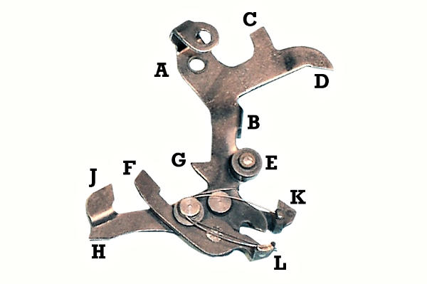
The carry lever is a complex assembly with 11 separate parts and a multitude of functions, but it measures less than 2" across the extremities.
A supports the lever on the same wire as the accumulator
backstop.
B is an attachment for a return spring which pulls the
assembly to the right (forward).
C is pulled up against a stop (the intermediate gear shaft)
to set the rest position.
D sits above the carry lever locking dog, to ensure that
the lever can not move rearward until a carry is required.
E is a roller of 3/16" diameter which rests in the hollow
of the "S" cam on the escapement wheel. The roller pushes the carry
lever about 3/16" to the left (rearward) as the escapement wheel
rotates, and the spring pulls it back again.
F-L is the carry operating pawl, pivoted at the bottom end
of the vertical lever and held clockwise against a stop by a fine
(0.009") hairspring. As the carry lever moves rearward, the pawl
F pushes against one of the pins of the lantern wheel and
rotates it one position clockwise.
G blocks the rotation of the lantern wheel as soon as the
carry is transferred, so as to prevent over-run.
H-J-K is the "duplex lever", which allows adjacent columns
to be operated simultaneously. It is pivoted above the carry pawl and
held anti-clockwise by a second hairspring.
H sits on the small roller at the bottom front of the
segment lever. It either follows vertically as the segment lever
moves, or rolls horizontally as the carry lever moves.
J is lifted between the bars of the lantern wheel to
prevent over-run as the segment lever completes its upstroke.
K rises as the segment lever is depressed, and blocks the
rotation of the escapement wheel until the segment lever returns to
its rest position (ie, it delays the incoming carry until the column
is ready to receive it).
L is raised by the subtraction cutoff lever, lowering the
carry pawl F and preventing the transfer of the carry.
 The carry lever operation.
This view shows the carry lever installed and in its rest position. Note that the carry gear and escapement wheel belong to the previous column. The escapement detent levers have been removed for clarity.
The carry lever is held forward (to the right) against its stop at C, with its roller resting in the hollow of the escapement "S" cam. The carry pawl F is spring-loaded upwards and rests lightly against the bars of the lantern wheel. The segment lever roller (lower left) holds the duplex lever raised, with the locking tooth J blocking any movement of the accumulator.
There are four possible sequences of operation:
 The carry lever locking dog.
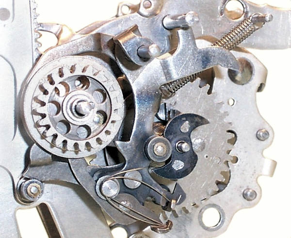
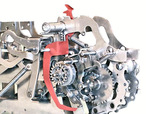
This view shows the carry lever and the escapement wheel from the front right-hand side, with the carry gear and spring removed for clarity.
The "carry lever locking dog" (red) is an auxilliary mechanism which locks the body of the carry lever in its home position until a carry is required. In particular, it resists the tendency of the over-run detent J to pull the carry lever rearward as it absorbs the rotational energy of the gear train at the end of the cycle.
The locking dog is riveted to the rock frame side plate at the centre left. The coil spring on the lower arm holds the lever clockwise. The "dog" on the top of the upper arm sits under the tail D of the carry lever and locks it in its home position.
The rearward horizontal arm of the locking dog sits above the inner "S" cam on the escapement wheel. When a carry is required, the escapement wheel rotates clockwise (in this view). The inner cam flicks the locking dog out of the way, so that the outer cam can drive the carry lever rearward.
This view also shows the duplex lever, which rises to block the movement of the escapement wheel as soon as the segment lever moves downwards.
Also visible is the setting of the deep tooth on the accumulator
pinion, one place forward of top with the segment lever at rest.
 The subtraction cut-off lever.
The subtraction cut-off lever is an operator control which inhibits the carry transfer from the left-most active column during subtraction, avoiding the need to left-fill the keyboard with nines.
The lever is a 3" long vertical arm pivoted just behind the segment rack. The upper section is offset to pass behind the side plate, and presents a small finger tab between and behind the numeral wheels at the front of the machine. The operating tab is held forward by a stiff spring attached to the frame plate.
The lower arm of the cut-off lever ends in a curved horizontal section just below the tag L on the forward end of the carry transfer pawl. Pressing the finger tab raises the lower end of the cut-off lever, forcing the upper end of the carry pawl downwards and clear of the lantern wheel pins.
With the tab held pressed during a carry operation, the tag L slides along the oiled surface of the horizontal arm, keeping the operating pawl clear of the lantern wheel. The escapement and carry lever perform their normal movements, but the carry is not transferred to the accumulator.