 Overview.
At its most basic level, the Comptometer addition mechanism consists of a rack-and-pinion drive and a one-way ratchet which converts the vertical motion of the keys into a corresponding forward rotation of the numerals. The Comptometer only counts forward, even during subtraction.
A long horizontal "segment lever" is pivoted at the rear of the machine and supported by two large coil springs. The keys press the lever downwards against the tension of the springs. A toothed rack or gear segment on the front of the lever drives the pinion and ratchet, which drives the numeral wheel through a train of intermediate gears.
The mechanism is designed to avoid damage from over-vigorous operation by free-wheeling on the downwards keystroke. The ratchet engages and advances the gear train in an orderly manner as the segment lever is lifted back by the springs on the return stroke.
Overview.
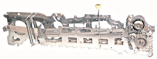
This view shows the general arrangement of the keys, the segment lever, and the gear train for one column of the machine. All other components and mechanisms have been removed for clarity. Each item is described in detail in the sections following.
 The segment lever.
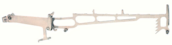
The segment lever is made from heavy (0.051") steel, and measures just under 12 inches long. It is carried on a pivot wire of 0.108" diameter at the rear of the machine, and is supported by two coil springs attached to the lower cross-arms.
The vertical section at the front of the lever is forged into a gear segment or rack. The segment has 19 teeth at 0.075" (approx) pitch, and is permanently engaged with a matching pinion on the accumulator assembly.
The nine small raised sections on the long horizontal surface of the lever act as bearing surfaces for tags or shoulders on the right-hand side of the keystems. The two larger projections and the bell crank arm (rear quarter) are part of the "controlled key" mechanism; the large saw-tooth rack near the front is part of the key stop mechanism.
 The accumulator assembly.
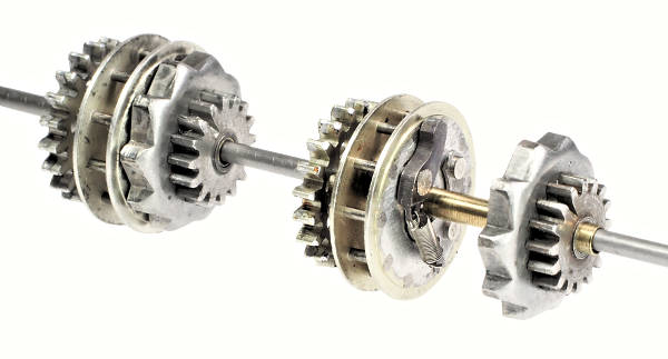
The gear train starts with the accumulator assembly, which consists of five separate sections. From right to left:
The unit on the left shows the complete assembly. The accumulator on the right has been slid apart to show the ratchet pawl and spring, and the brass bushing sleeve between the gears and the shaft.
Further details of the gear ratios and timing are given in the Sterling models section.
 The gear train.
On a decimal column, the gear train which drives the numeral wheel consists of:
The numeral wheel is a celluloid moulding with painted numbers, attached to a lightweight metal pressing.
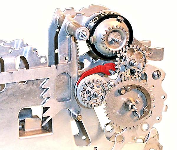
The large carry gear is mounted on a separate sub-frame (the rock frame) which hangs from the intermediate gear shaft. The carry gear, intermediate gear, and numeral wheel gear are permanently meshed, but the rock frame can be swung forward to disengage the carry gear from the accumulator to allow the numerals to return to zero (described further in the Clearing section).
As the key presses the segment lever down, the pinion rotates anti-clockwise and the pinion ratchet free-wheels. A spring-loaded detent or "backstop" (red) at the top of the lantern wheel prevents the accumulator from rotating backwards.
As the segment lever rises on the return stroke, the pinion ratchet drives the accumulator forward (clockwise), advancing the gear train and the numeral wheel. The backstop, brake, and carry mechanism (described later) provide a combination of spring and friction loading to control the speed of return. At the end of the upstroke, the small roller on the bottom front of the segment lever pushes a detent (not shown) between the pins of the lantern wheel to prevent over-run (described further in the Carry section).
The top frame spacer tube (behind the numeral wheel) acts as an upper stop for the gear segment. An eccentric section on the tube allows for fine adjustment of the rest position, so that the ratchet and backstop will operate correctly with minimal lost motion. The rest position is also important to the operation of the carry mechanism and the error correction mechanism.
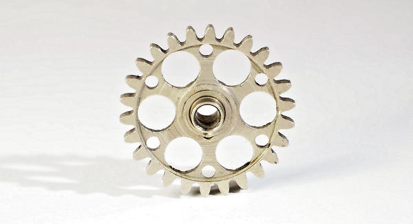 The intermediate gear.
In working with the Comptometer, one is frequently struck by components which excel in both form and function to become things of beauty in their own right.
This intermediate gear is one such example, where a relatively insignificant component has been transformed into a classic of 19th-century engineering design.
Whether it be in the elegant decoration of the casework, the graceful curves of the frame plates, or the attention to detail in components that would never be seen by the owner or operator, one is constantly reminded that the designer of this equipment saw his Comptometer not just as a machine but as a work of art.