John Wolff's Web Museum
Anita Model 1011-LSI Desk Calculator
Contents
|
|
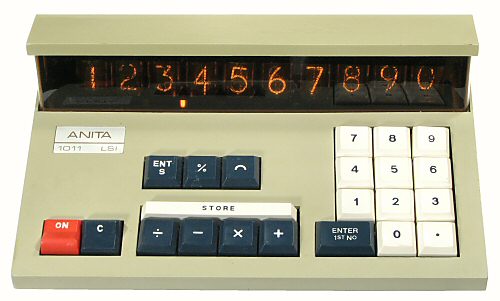
Anita Model 1011-LSI, S/N LM 107206
Functions: ASMD, constant, percent, roundoff, 1 memory
Technology: MOS-LSI, 5 chips
Display: 10 digits, Nixie tubes
Dimensions: 225W x 140D x 90H, weight 1.0kg
Manufactured: Bell Punch Company, England, 1971-
|
Overview
The Bell Punch Company of
England is generally credited with building the first production
electronic calculator - the ANITA - in 1962. The first ANITA was a
full-keyboard machine using vacuum tube technology, modelled on the
existing Sumlock
mechanical comptometers.
The "1000 Series" of solid-state 10-key machines was introduced
towards the end of 1969. The basic machine was a 10-digit
four-function desk calculator, with the different models in the
series offering different combinations of features - constants,
square roots, percentages, or a single memory register. The circuitry
was implemented primarily with discrete-component diode and transistor
logic, with a small number of MOS integrated circuits to provide the
storage registers. The circuit design and the keyboard interface used
the "postfix" or "reverse Polish" logic system.
The 1000-LSI series from 1971 replicated the functions of the
1000-series machines in less than a fifth of the volume by using
the new MOS-LSI integrated circuit technology. The LSI machines used
only 5 custom-built IC chips and about 40 transistors to replace the
previous thousands of discrete components.
This page gives a brief overview of the construction, circuitry,
and operation of the Anita Model 1011-LSI. A
similar page describes the
workings of the earlier discrete-component version, the Model 1011.
The descriptions are based primarily on my own observations and
interpretations, supplemented by reference to the 1011-LSI instruction
manual and some of the US patent documents. Corrections, comments, or
further information are welcome via the
Enquiry Form.
Construction
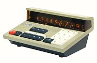
 External view
The calculator is housed in a simple 2-piece plastic casing. The
two sections are held together by moulded clips at the rear and two
screws from underneath at the front. The distinctive styling is
dominated by the full-size Nixie-tube display and the "wrap-around
windscreen" (which was popular on the cars from the same period).
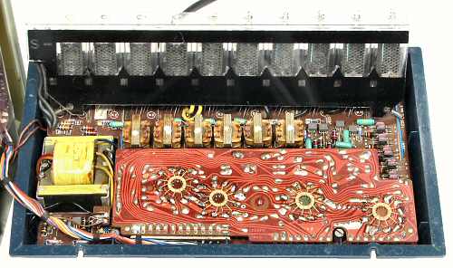 Internal view
The keyboard assembly is mounted in the upper section of the case.
The power transformer and three circuit boards are in the lower
section. The main board is secured by moulded clips at the rear and
two screws at the front. The keyboard is attached by an 11-core cable
and pin-and-socket connectors.
Circuitry
This section describes the physical circuitry of the machine. I have
also prepared a set of reverse-engineered schematic drawings which can
be made available to interested parties on request. These show all of
the discrete-component circuitry, including the keyboard and display
multiplexing arrangements and the communication paths between the IC's.
Unfortunately neither the schematics nor the operating instructions
give any information about the overall logical structure of the machine
or the internals of the IC chips. The available patents describe
various individual features, some in infinite detail, which may or may
not apply to the early Anitas, the 10-key machines, the 1000 series,
or the 1000-LSI. It appears that all the machines operate in a similar
manner using a pulse-counting system, but for the moment I do not
propose to investigate any further.
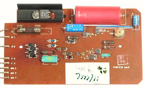 The power supply board
The power supply board is mounted in the bottom of the lower
section of the case. It produces a single regulated +15V DC supply,
and includes a protection circuit to shut down the regulator in
case of overload or short-circuit. There is no 200V DC supply for
the Nixie tubes, as the necesary high voltages are generated
on-the-fly by pulse transformers in the multiplexing circuit. The
total current drain from the power supply is only about 250mA at
15V, or less than 4W.
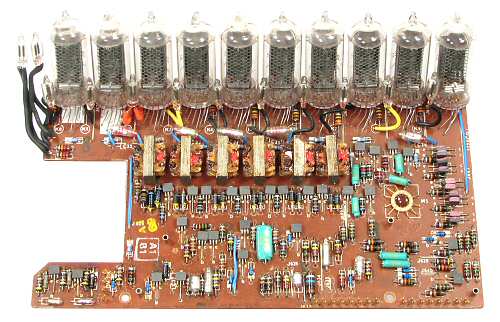 Main circuit board
The main circuit board measures 100 x 195mm. The ten ZM1082 Nixie
tubes are mounted at the rear, with individual neon lamps to form
the decimal points. There are two separate neons at the left for
Store and Minus indicators. The display always shows the full ten
digits, left-aligned with trailing zeros.
The anodes of the ten display tubes and the two indicators are
driven from the six pulse transformers and associated transistors
near the centre of the board. The cathode drivers are along the
right-hand side, with the controlling IC mounted upside-down through
a hole in the board. The "odds and evens" multiplexing system is
outlined in US Patent 366987, filed by James Drage of Sumlock in
November 1970.
The main board also carries part of the keyboard pulse shaping
syatem and the master clock generator. The clock generator (in the
front left corner) is a simple multivibrator which produces a
single-phase square wave at about 330Khz.
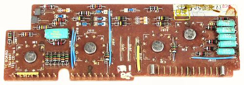 IC board
The IC board measures 55 x 155mm. It mounts above the main board
with the component side down, and attaches via the vertical pin
connectors at the lower left. The keyboard cable attaches to the
horizontal pins at the right. The under side of the board is visible
in the Internal View above.
The ICs were custom-built by General Instrument Microelectronics
(GIM) to replicate the functions of the earlier Anita 1011. The chips
are housed in 12-pin metal-can packages which are mounted upside-down
through the board. The IC numbers in this machine are 201C2, 261L1,
241L2P, and 161C10 on the IC board, and 121T1 as the display controller
on the main board.
Apart from the power and clock signals, there are only three data
lines interconnecting the five IC chips. The internal data signals are
multiplexed onto these three lines and transmitted serially. The
multiplexing arrangement is outlined in US Patent 3683415, filed by
Lloyd and Letheren of Sumlock in November 1970.
 Keyboard PCB
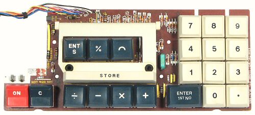
The keyboard PCB measures 85 x 200mm, and contains the key switches
and a diode encoding matrix. The connecting cable plugs in to the IC
board. The power switch at the left has two separate quick-connect
spade lugs which carry the incoming mains voltage.
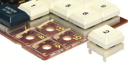 Key switch detail
The keyboard uses simple mechanical switches with a bronze spring
and a fixed stud mounted directly onto the circuit board. The keytops
and return springs are mounted on a 3-legged base which clips into
slots in the board. The keytops are easily removed for cleaning. The
input circuit includes an R-C filter to eliminate contact bounce.
Operation
The instruction manual for the 1011-LSI gives examples of keystroke
sequences for performing various types of calculations, but provides
no information at all about the overall architecture of the machine
or the internal register operations. The notes following summarise
what appears to happen in response to the function keys.
The calculator operates according to the "reverse Polish" logic
system. For the four basic functions:
- key the first number (stored in the display register)
- press "Enter 1st Number" (copies the number
to an internal register)
- key the second number (if any)
- press a function key ASMD (performs the operation
on the two registers and displays the result).
Chain calculations can be continued in similar fashion.
The "C" (for Constant) key is a switch which copies the display
to the internal register and locks the contents for use in a series
of calculations. It is also useful with the Percent key.
For example, to calculate 50 + 5%:
- 50 C (copies 50 to internal register and locks)
- 5 % X (calculates 5% of 50, displays 2.5)
- + (adds the display to the retained 50, displays 52.5)
Strange results will follow if the C switch is accidentally left down
during the next calculation.
A third "Store" or memory register is accessed through the "EntS"
and "Store" keys. EntS copies the current display into the store
register, overwriting the previous contents. The Store key recalls
the contents of the register and lights the Store indicator until
one of the adjacent ASMD keys is pressed. The Add and Subtract keys
return their results to the store to provide an accumulation function,
while Multiply and Divide leave the store unchanged. For example:
- 2 Ent 1st 3 X Ent S
(calculates product 6, copies to store)
- 4 Ent 1st 5 X Store +
(calculates product 20, adds to store, displays 26)
- 2 Ent 1st Store X
(multiplies store by 2, displays 52, store remains at 26)
The blue key marked with the arch or semicircle rounds the display
to two figures after the decimal point.
The calculator normally operates to 10 significant figures, which
are displayed left-aligned with trailing zeros. The decimal point
floats within this range. For out-of-range results with more than 10
figures to the left of the decimal point or 10 zeros to the right, the
machine still displays 10 significant figures but shifts the decimal
point 10 places in the appropriate direction, giving an effective
20-digit operating range.
Resources for further information
- The Bell Punch Company page
gives an overview of the company history and shows a selection of PLUS,
Sumlock, and Anita calculators.
- The Technical Section of this site
has descriptions of the workings of the "PLUS" mechanical calculator
and the transistor-based Anita 1011 electronic calculator.
- Nigel Tout from England has a very detailed history of the rise
and fall of the Bell Punch Company in his
Anita Calculators web site.
He has illustrations of many of their other models, both mechanical
and electronic, and tells the fascinating story of how a bus-ticket
company came to build the world's first electronic calculator.
Original text and images Copyright © John Wolff 2009-18.
Use at own risk; beware of errors; suggestions for improvement welcome.
Last Updated: 16 April 2018
Back to:
Home
Calculating Machines
The Bell Punch Company
Tech Index