 Olympia Model CD-200, S/N 0108225
Functions: ASMD, K
Technology: MOS-LSI (Solitron, 5 chips)
Display: 10 digit, Nixie tubes
Dimensions: 380W x 150D x 80H, weight 1.8kg
Manufactured: Made in Japan for Olympia, late 1971.
Olympia Model CD-200, S/N 0108225
Functions: ASMD, K
Technology: MOS-LSI (Solitron, 5 chips)
Display: 10 digit, Nixie tubes
Dimensions: 380W x 150D x 80H, weight 1.8kg
Manufactured: Made in Japan for Olympia, late 1971.
The Olympia organisation developed from the Union Typewriter Company, established by AEG in Berlin in 1903. Mechanical adding and calculating machines were introduced in the late 1940s. Olympia reached its peak in around 1970, but collapsed shortly afterwards as Japanese calculators and computer-based word processors put an end to its traditional office machine markets.
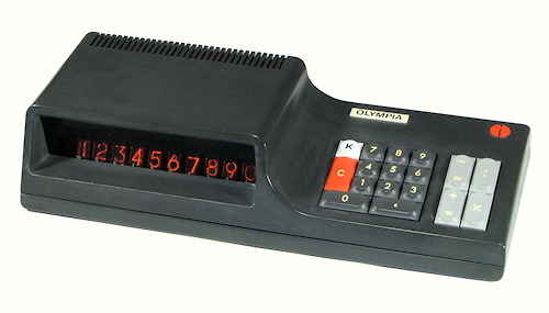
The CD-200 was made in Japan for Olympia in late 1971, most probably by the Matsushita organisation (later National/Panasonic). It is a basic four-function desk calculator with a 10-digit Nixie-style display. The logic circuitry is based on a set of five MOS-LSI chips manufactured by the American Solitron company.
External view
The CD-200 is quite a large desktop machine which measures 380mm wide, 150mm deep, and 80mm high. The weight is about 1.8kg. The machine has an unusual and aesthetically "interesting" design, with the display located forward and to the left of the keyboard.
The machine is labelled as having been made in Japan for Olympia Werke AG, Wilhelmshaven. There is no serial number on the nameplate, but the number 0108225 is stamped on the power supply chassis.
Operation of the CD-200 is quite straightforward, as it has only the four basic arithmetic operations and a latching Constant key.
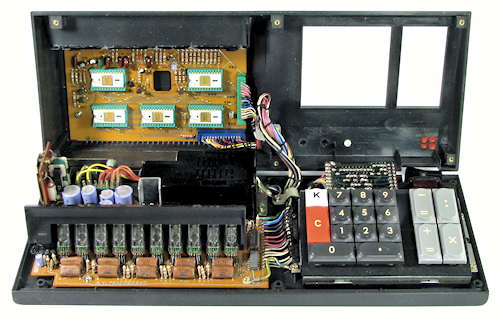 Internal view
In another unusual arrangement, the display and keyboard are mounted in the bottom section of the case, and the processor board is mounted component-side down in the upper section - where it collects the heat from the power supply and display tubes. (The rectangular cut-out in the centre of the processor board actually serves to locate the top of the U-section heatsink attached to the main regulating transistor).
The mains-power components are mounted on a metal chassis at the left-hand rear of the machine, with a mains switch at the right-hand rear corner.
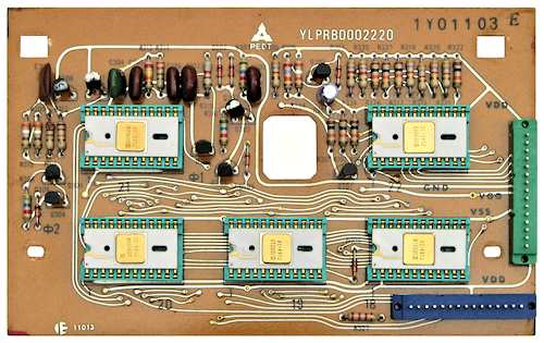 CPU board
The processor is built on a double-sided phenolic board measuring 105x170mm. The board carries five MOS-LSI chips in 24-pin ceramic packages, 9 discrete transistors, and a small collection of passive components. The Matsushita triangle logo is etched into the front of the board.
The main chips are numbered SD9018, SD9019, SD9020A, SD9021, and SD9022, with date codes from 7144 to 7151 - ie, November and December of 1971. The "SD" prefix and "S" logo indicate that they were made by Solitron, which at that time was a small general-purpose semiconductor manufacturer. The company is still in business making power electronic devices.
The timing signals are generated by a transistor oscillator at the upper left of the board. The master clock runs at a leisurely 70kHz.
The processor board connects to the display and keyboard via two 16-pin headers at the lower right. The connectors are colour-coded (blue for keyboard, green for display), but are not keyed or polarised.
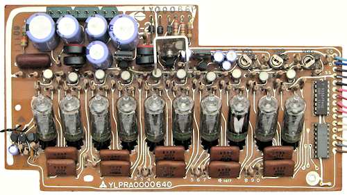 Display board
The display board is another double-sided phenolic board measuring 105x190mm. The display tubes (Matsushita CD88P, all dated April 1971) are 12.5mm in diameter and 30mm tall, with numerals 12mm high. A miniature incandescent lamp for negative indication is attached by flying leads at the front left.
Behind the display tubes are the 10 A617 high-voltage transistors for the anode drivers, and behind these are the power supply components. The power supply takes 3 separate AC inputs from the transformer via the connector at the rear of the board (behind the capacitors), and produces 3 logic supplies (VSS +5V, VDD -8V, VGG -22V) and a +200V supply for the display tubes. The three logic supplies are individually adjustable via the trimpots at the upper right.
At the right of the board is a 7442 TTL BCD-to-decimal decoder for the anodes, and a Signetics CC1939 decoder/driver for the cathodes.
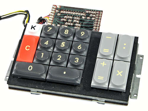 Keyboard
The keyboard uses glass reed switches operated by moving magnets on the ends of the keystems. The keys are mounted on a substantial pressed-metal frame about 130 x 95mm, with the reed switches on a circuit board below. The circuit board has an extension at the rear which carries a diode encoding matrix, which compresses the 17 key contacts into only 10 wires. These then connect to the blue plug on the processor board.
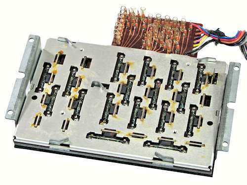 Keyboard underside
This underneath view shows the arrangement of the reed switches and the diode encoding matrix. The underside of the keyboard is normally covered with a rigid plastic moulding to protect the switches.
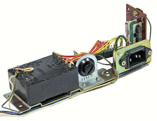 Power supply chassis
The mains-voltage components are mounted on a metal chassis at the left-hand rear of the machine. The unit has an IEC input socket, a line filter, a fuse holder, and an On/Off switch on a flying lead. The potted mains transformer has re-wirable primaries for 100 to 240 V AC, and three isolated secondaries which connect to the rectifiers and regulators on the main circuit board. A rigid plastic cover (removed for illustration) provides insulation and protection for the transformer and the fuseholder. The power consumption is rated at 9W.