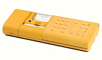
 Olivetti Divisumma 18, S/N 0062710
Functions: ASMD, printer, battery powered
Technology: MOS-LSI (2 chips)
Display: Internal printer, no numerical display
Dimensions: 250W x 120D x 50H, weight 920g
Manufactured: Olivetti, Italy, 1973
 Olivetti Divisumma 18, S/N 0062710
Functions: ASMD, printer, battery powered
Technology: MOS-LSI (2 chips)
Display: Internal printer, no numerical display
Dimensions: 250W x 120D x 50H, weight 920g
Manufactured: Olivetti, Italy, 1973
This page gives a brief description of the construction and operation of the Olivetti "Divisumma 18" electronic calculator from 1973. General information about the Olivetti company and other Olivetti calculators can be found on the main Olivetti page.
The Divisumma 18 (D18) is a portable battery-powered calculator which performs only the four basic arithmetic functions. An internal printer records all entries and results, but there is no separate numeric display. The calculator is known mainly for its radical styling, and in particular for the soft-touch rubber moulding which covers the whole of the keyboard area.
To put the D18 in perspective, readers may find it helpful to review the progression of machines on the main Olivetti page, and the internal descriptions of the earlier Logos 200 and Logos 50/60 electronic calculators.
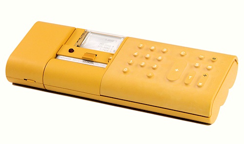 External view.
The Divisumma 18 is built in two sections. The main body containing the keyboard and printer measures 250mm wide x 120 deep x 50 high and weighs 920g. The detachable battery charger on the left-hand side adds 60mm to the length and brings the total weight to 1320g.
To the left of the keyboard is a sliding On/Off switch and a selector for 0, 2, 3, or 4 fixed decimal places. A red lamp at the far left doubles as an error indicator and a low-battery warning.
The exterior of the D18 is the work of the noted architect and industrial designer Mario Bellini (1935- ). The machine is shown in his US design patent D233350, which was originally filed in Italy in December 1972. The Museum of Modern Art in New York features a Divisumma 18 in its permanent collection.
The rubberised keyboard was also used in a mains-powered desktop calculator (the Divisumma 28, design patent D233349), which was finished in a more conservative dark grey.
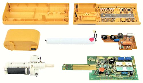 Components.
The D18 continues the principles of modular design from Olivetti's earlier "Logos" machines. This view shows the main components.
At the top are the two halves of the moulded plastic casing, with the keyboard switches mounted in the upper half.
In the centre row are the battery charger module, the battery of four Sub-C NiCad cells, and the power supply inverter board. The charger module contains only a transformer, which supplies 12V AC to the circuitry on the main board.
In the foreground are the printer mechanism and the main circuit board.
(Note: To open the D18 case, do not attempt to remove the four rubber feet. Rather, insert a flat-blade screwdriver about 2-3mm wide through the hole in the centre of each foot and remove the foot and the hidden screw together).
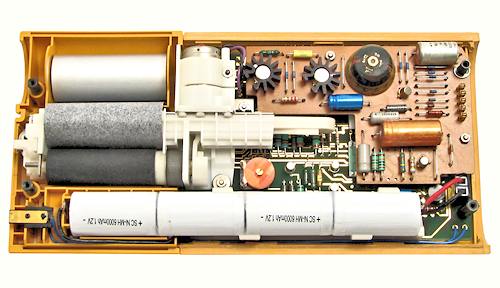 Internal view.
All of the components of the D18 are assembled in the upper section of the case. The lower section provides additional support for the battery, and contains a hinged door for loading the paper roll. The battery charger clips on to the left-hand end, and connects to the main board via the contacts at the lower left-hand corner. The battery pack clips into a plastic holder and has a plug-and-socket connection to the main circuit board. The battery illustrated has been rebuilt with new cells. (The original battery is shown in the component view above).
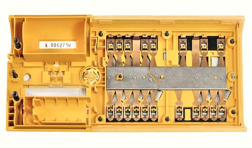 The keyboard mechanism.
The keyboard uses two rows of metal leaf-springs which make contact with gold-plated pads on the under side of the main circuit board. A system of diagonal rocking bars set into the underside of the top cover provides a mechanical translation between the keypad button matrix and the two straight-line rows of contacts.
Each contact is fitted with a separate over-centre spring. Although the rubber keytops are soft to the touch, the springs give the keys a very light and positive snap action, with an audible click to confirm operation.
The contacts for the On/Off switch and the rotary decimal selector are at the centre left, and these also bear directly on gold-plated pads on the main board.
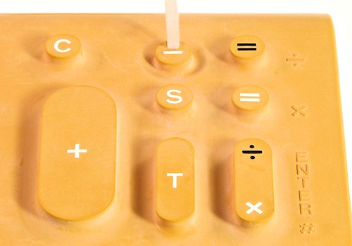 Keyboard detail.
This close-up view shows the profile of the key buttons, with the Minus key shown depressed.
Addition and subtraction operate in adding-machine fashion, with numbers being printed as they are entered into the register. C is a correction key which clears the whole of the current entry. The Total (T) key prints the result and clears the register; Sub-total (S) prints the contents and leaves the register unchanged. To encourage the habit of always pressing Total before starting a calculation, the D18 is made to power up with the error lamp lit, so that Total must be pressed before the machine can be used.
Multiplication and division can be entered algebraically using the colour-coded legends printed on the keytops. For example, to multiply 2 by 3, use the white legends and press 2 X 3 =. For operators familiar with the "reverse Polish" entry of the earlier machines, using the moulded legends to the right of the keys will produce the same key sequence and the same result: 2 Enter 3 X . (There is only a single key switch under the Mult/Div/Enter button).
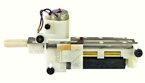 The printer mechanism.
The D18 uses a small electrosensitive dot-matrix printer of Olivetti's own design. The principle is described in US Patent 3826915, first filed in Italy in September 1971. The printer uses a special "metallised" paper which is coated with a very thin layer of carbon black and then a top layer of aluminium. The print head consists of seven hardened pins which are lightly in contact with the aluminium layer. As the print head is swept across the paper, a series of high-voltage impulses are applied to the pins to vaporise the aluminium at the required dot positions. This allows the black layer to show through to form the dot-matrix characters.
The illustration shows the D18 printer mechanism from underneath. The motor and head traverse mechanisms are at the top, and the platen roller at the bottom. The print head is at the bottom of the T-shaped plate, adjacent to the platen roller. The signals to the print head are communicated through seven wire fingers (at the left of the head assembly), which run along matching tracks on the main circuit board. Three bronze fingers provide the ground connection and a home position signal. The motor connects directly to two pins on the main board.
All of the printer timing and control circuits are on the main circuit board. There are no electronic components in the printer module itself.
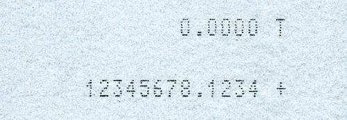 Printer output.
The D18 calculates to a maximum of 12 significant figures, with 0, 2, 3, or 4 fixed decimal places.
The printer mechanism produces clear 5x7 dot-matrix characters which are 3mm high. The lines are spaced 5mm apart. The lines are printed from right to left and include a symbol, space, decimal point (if selected), and up to 12 significant figures.
The print cycle takes about 800mS, regardless of the number of digits. Clearing the machine by taking a Total also prints a blank separator line, and thus takes 1.6 seconds.
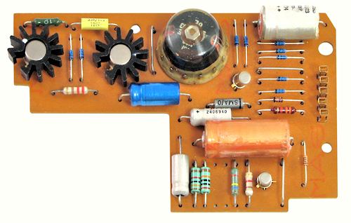 The inverter board.
The power supply inverter is built on a single-sided board measuring 115x75mm. The PNP switching transistors operate at only 4kHz, driving a pot-core transformer which is fully encapsulated in epoxy. Two secondary windings produce negative supplies for the logic circuits and the printer. An under-voltage circuit monitors the logic supply and shuts down the inverter if the output falls below a safe voltage. (The shut-down circuit is independent of the low-battery warning).
The inverter board connects to the main board through five
pin-and-socket connections at the right-hand side. The connections are:
5 (Top) Ground - battery negative.
4 Logic supply -23V DC
3 Printer supply -40VDC
2 Shut-down
1 (Bottom) +5V - battery positive.
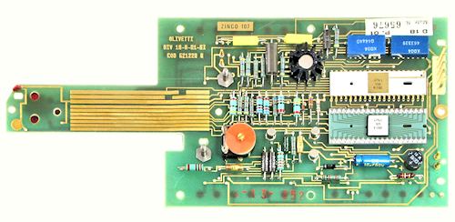 The main circuit board.
The body of the main circuit board measures 155x100mm, with a 75mm extension at the left-hand side. The board is heavily gold plated on both sides - the front for the printer tracks, and the rear for the control switches and keyboard. The two rows of contact pads for the key switches are visible along the top and bottom of the under side of the board.
The two 40-pin LSI chips are made by SGS (an Olivetti subsidiary at one time) and are labelled 2051A and 2052B. The printer interface (along the top of the board) uses two 16-pin driver modules labelled K004. The 2-transistor clock oscillator at the lower left produces complementary square-wave signals (+5V/-10V) at about 250kHz.
The 12V AC input from the charger socket is hard-wired to the two pads at the bottom right of the board. The battery connects to two pins directly above. The inverter board connects to the five pins at the top right, while the printer motor connects to two pins at the top left.
The original battery contained four Sub-C NiCad cells of unknown capacity. With a new fully-charged (5V) battery the calculator draws about 250mA or 1.25W when idle, and 400mA or 2W while printing. Modern Sub-C cells of 6Ah capacity could theoretically power the calculator for 15 hours of continuous printing.
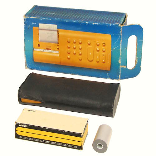 Divisumma 18 accessories.
This view shows some of the D18 accessories. The original packing box measures 300mm long x 180 wide x 100 high, and has a built-in carrying handle. A soft case or sleeve was provided for the calculator itself, less charger. The case has solid ends with press-stud fastenings, but has no strap or handle.
The special metallised printing paper was supplied by Olivetti in boxes of five rolls, each 60mm wide and about 35mm in diameter. Each roll contains about 20m of paper, which is sufficient to print 4000 lines. Similar metallised paper was quite widely used in other 1970s printing mechanisms, and is still available from several sources.