John Wolff's Web Museum
The Compucorp 320 series "Micro Scientist"
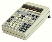 Compucorp Model 324G "Micro Scientist", S/N 4201133
Functions: Scientific, programmable, 10 memories
Programming: 2 x 80 steps, all keystrokes, no conditionals
Technology: MOS-LSI by Texas Instruments, MOS memory
Display: 13 significant digits plus 2 exponent, 7-segment Panaplex
Dimensions: 135W x 230D x 75H, weight 1.15kg (without batteries)
Manufactured: Compucorp USA, 1973.
Overview
The Computer Design Corporation of Los Angeles
introduced several models of portable battery-powered calculators in
the early 1970s. This Model 324G "Micro Scientist" was made in 1973.
Its accuracy, range, functionality, and programmability were very
advanced for the time, as were its portability and ease of use.
The instruction booklet is clear, concise, and rather irreverent, and
explains everything in only 26 small pages (5" x 7").
Construction
The calculator is built in a compact plastic case with
very little wasted space. The four printed circuit boards are stacked one
above another in the area under the keyboard, and plug into a backplane
across the centre of the machine. The double-sided boards have a
component area of 5" x 4-3/4". The battery compartment holds four D-size
NiCads, and occupies the section below and behind the Panaplex display.
The perspex cover over the display can be lifted to allow direct
viewing. There is a fold-out carrying handle at the rear, along with
the power switch and the charger or mains adaptor input. There is a label
with abbreviated operating instructions underneath. Overall, the calculator
gives the impression of being well designed and well constructed.
Circuitry
The circuitry is based on seven 40-pin MOS-LSI chips
from Texas instruments, accommodated on four circuit boards. The boards
are labelled (from bottom to top): Supply, Memory, Processor, and Scan.
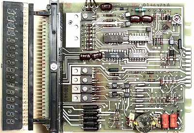 Power Supply Board
The illustration shows the 16-digit Panaplex display at the left,
then the vertical backplane and the power supply board. There are two
off-board cables with in-line plug and socket connectors for the battery
input and the high-voltage output to the display drivers. There is no
connection to the contacts at the right-hand end of the board.
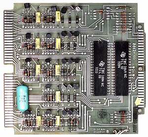
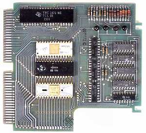 Memory Board
The LSI chips on the memory board are the Texas Instruments
TMC1871NC in the 40-pin package, and 3 ROM chips in the 28-pin
packages. There is provision for a fourth ROM package at the lower
edge of the board. There are four Intel P2102 1k x 1bit static
RAM chips, and 4 support chips. The cutout at the bottom of the
board is to clear the transformer on the power supply below.
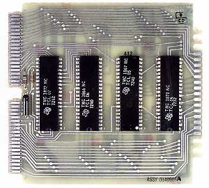 Processor Board
The processor board contains four Texas Instruments LSI chips
in 40-pin packages. The part numbers are (from left to right):
TMC1872, 1866, 1867, and 1870. There is no connection to the contacts
at the right-hand end of the board.
 Scan Board
The scan board handles both the keyboard and the display.
There are two LSI chips (TMC1869 and 1884) in 40-pin packages, and 24
discrete transistors. The display is driven through the backplane
connector at the left, while the keyboard is attached via a 28-way
flexible ribbon from the right-hand end.
Keyboard Operation
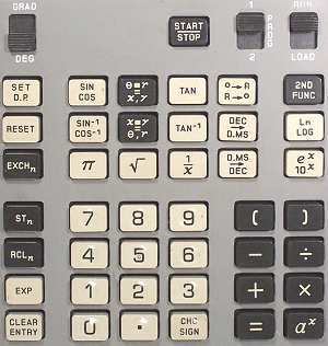 The 324G keyboard is largely self-explanatory.
The calculator uses "algebraic" data entry, with parentheses that
can be nested two levels deep.
The 324G keyboard is largely self-explanatory.
The calculator uses "algebraic" data entry, with parentheses that
can be nested two levels deep.
However, the "2nd FUNC" key is unusual in that it is a postfix
rather than a prefix. Entering 30 and pressing SIN-COS will calculate
both functions, store them internally, and display the first. If you
wanted COS, press 2nd FUNC. Pressing 2nd FUNC repeatedly will
alternate between the two results.
The two internal result registers are used to advantage with (eg) the
rectangular to polar conversions at the top of the third column, where the
instructions are actually printed on the keys. The topmost key reads:
enter the angle, press the key, enter the radius, press equals, display
shows x, press 2nd FUNC to show y.
The Store, Recall, and Exchange keys in the first column function as
expected with the ten memory registers, but also allow extensive register
arithmetic. For example, the keystrokes 4 STn 2 will store 4 into register
2, while 4 STn X 2 will multiply the contents of register 2 by 4.
The same basic keyboard was used for several different models. The
programming keys were deleted on the Model 320; the PROG 1 or 2
selector was only used on model 324; the GRAD/DEG switch was only on
G-suffix models. The Model 324 actually has two more slider switches
hidden under the escutcheon at the top of the second and third keyboard
columns, possibly intended for use with the missing fourth ROM.
Programming
Programming the "Micro Scientist" is simply a matter of
setting the LOAD/RUN switch (top right) to LOAD and recording the
keystrokes needed to solve the problem. The START/STOP key is used to
pause execution for data entry or reading of results.
The display shows a 2-digit step counter on the right-hand side while
recording is in progress, but there is no provision to review or edit
the program. If a mistake is suspected, switch back to LOAD and start
again.
Although there are no conditional or jump instructions, the user's
manual describes a simple technique for writing iterative programs. The
results of each iteration are stored in the memory registers, and the
loop counter can be tested for zero with the 1/x instruction, or for
negative values with the square root instruction. Either case will force
an error and halt the program, after which the results can be retrieved
manually (or by a second program, on the model 324).
Original text and images Copyright © John Wolff 2002.
Use at own risk; beware of errors; suggestions for improvement welcome.
Last Updated: 30 June 2002
Back to:
Home
Calculating Machines
Compucorp
Tech Index
 Compucorp Model 324G "Micro Scientist", S/N 4201133