John Wolff's Web Museum
Compucorp 155 "Surveyor" Desk Calculator
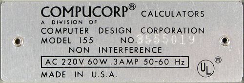
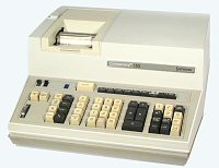 Compucorp Model 155 "Surveyor", S/N 3555019
Functions: Scientific, programmable, special surveying functions
Programming: Keyboard or external 80-column card reader
Technology: MOS-LSI (AMI, 30 chips)
Display: 21-column impact printer, 8-bit register display
Dimensions: 380W x 405D x 175H, weight 10.9kg
Manufactured: Computer Design Corporation, Los Angeles, January 1972
Original Owners: John B White Pty Ltd, Sydney, Australia
Overview
 The Model 155 "Surveyor" from 1971-2 is one of Compucorp's first
generation of programmable scientific desk calculators. All of the
100-series machines have a common computer-like architecture based on
a set of 18 custom-designed MOS-LSI chips. The basic design was then
customised for specific industries (science, statistics, surveying,
etc) by changing the internal program ROMs and the keyboard layouts.
The machines were available with either a numeric (Nixie tube) display
or an internal printer, but not both. A similar range of machines
customised for commercial applications was sold as the 200 series.
The Model 155 "Surveyor" from 1971-2 is one of Compucorp's first
generation of programmable scientific desk calculators. All of the
100-series machines have a common computer-like architecture based on
a set of 18 custom-designed MOS-LSI chips. The basic design was then
customised for specific industries (science, statistics, surveying,
etc) by changing the internal program ROMs and the keyboard layouts.
The machines were available with either a numeric (Nixie tube) display
or an internal printer, but not both. A similar range of machines
customised for commercial applications was sold as the 200 series.
The 100-series machines all provided scientific notation, trig and
log funtions, powers and roots, and multiple storage registers with
register arithmetic. The specialised functions on this Model 155
"Surveyor" include calculations of bearings, traverses, and rectangular
to polar conversions.
The machine described here was donated to the museum by
John B White Pty Ltd,
Consulting Surveyors, of Sydney, Australia. It was purchased
new in 1972, and was used regularly for survey computations including
closes, areas, adding & subtracting bearings, missing bearings and
distances, calculating joins between co-ordinates, calculating curves,
and various conversions. To do a property close it took around 8 punch
cards! The Compucorp was retired in around 1979 in favour of the
new HP-25C programmable pocket calculators.
This page gives a brief overview of the construction,
circuitry, and operation of the Compucorp "Surveyor" Model 155.
Construction
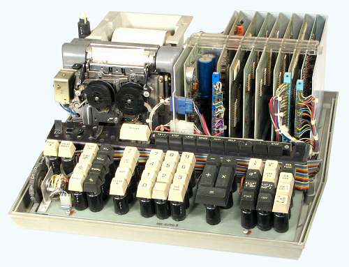 Internal view
This view shows the internals of the machine with the cover removed.
The printer mechanism and paper roll tray occupy the left rear
section of the machine. The power supply regulator board is in the
centre rear, with seven logic boards mounted vertically at the right.
The boards plug in to a horizontal backplane at the bottom and are
secured by a clear acrylic retainer at the top. Three of the boards
have additional edge connectors at the front for the printer, keyboard,
and card reader interfaces. The keyboard assembly occupies the front
section of the case.
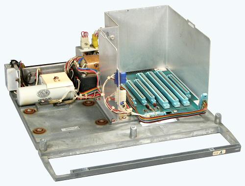 Chassis and power supply
The machine is built on a substantial die-cast chassis which
measures 355x380x12mm (approx).
The power transformer is mounted at the centre rear, with the line
filter and storage capacitors at the left. A mains voltage selector
plug is mounted above the transformer. Two MJE2955 regulator
transistors are bolted directly to the chassis (in front of the
capacitors). The power supply produces logic supplies of -15V
and -30V DC, and a 200V DC (approx) supply for the neon indicators.
The nameplate rating is
220V AC 60W.
The two plug-and-socket connectors at the front of the central
vertical panel carry the mains switch and 200V DC connections to the
keyboard assembly. The entire keyboard can be removed as a unit
with no extraneous leads or off-board connections.
The printer assembly is mounted on the four rubber bushings on
the left-hand side of the chassis, and the keyboard on the three
pillars at the front.
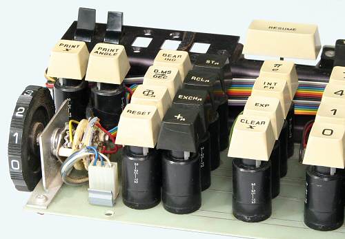 Keyboard construction
The main section of the keyboard is built using 43 individual key
switch modules. Each module contains a glass reed switch mounted
vertically along the central axis. The reed switch is surrounded by
a sliding collar and an annular magnet, which are pressed down by
the keystem above. The sliding collar is a fairly close fit in the
outer casing, which makes the switches susceptible to sticking when
dirt enters around the keystem. Three switches have previously been
replaced in this machine, and two more needed attention during
the overhaul.
The upper section of the keyboard contains the power and print
enable switches (left, with provision for two more), and a row of
push-buttons and indicators for use in programming. A rotary switch
at the left front selects 0 to 9 decimal places.
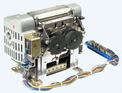 The EP-101 impact printer
The printing mechanism in the Compucorp "Surveyor" is historically
significant in its own right, being an OEM version of the classic
EP-101 impact printer - the device which launched the now-famous
Epson Corporation.
The EP-101 evolved from a printing timer that was developed by
the Seiko group for the Tokyo Olympic Games in 1964. Well over a
million units were built by the Shinshu Seiki Co. since it first went
on sale in 1968. The company adopted the "Epson" brand ("Son of
EP") for a new model in 1975, and became the Epson Corporation in 1982.
The printer has an open "pancake" motor and transistorised speed
controller under the left-hand cover. The motor operates at a nominal
17V DC, and drives a mainshaft across the rear of the machine at
3300 RPM. Gearing under the right-hand cover drives the print drum
at the top of the machine at 200 RPM. The drum is about 25mm in
diameter and 90mm long. It carries 336 raised numerals and
symbols in 16 rows of 21 characters. The rotating mechanism runs
continuously, but consumes only 2.5W and is almost silent when
properly maintained. It has significant inertia, and takes nearly
a minute to come to rest when the power is removed.
The 21 print hammers are located at the front of the rotating drum,
under the cover at the top of the ribbon mechanism. The hammers and
ribbon are in front of the paper, with the rotating print drum behind,
so that the drum remains clean and free of ink. The lower section
of the printer contains 21 small selector solenoids, arranged in three
banks of seven. Energising a solenoid pushes a selector lever forward
into the path of a flange on the rotating mainshaft. The flange flicks
the lever down as it passes, operating the hammer via a short linkage.
The hammer presses the ribbon and paper momentarily against the
rotating print drum as the required symbol passes under.
In this OEM version of the printer, the selector solenoids are
driven directly by the logic circuits in the calculator. Sensors on
the mainshaft and the print drum provide feedback signals to
synchronise the timing and sequencing. The calculator may have to
wait up to a full revolution of the drum (300mS) until the required
symbol reaches the printing position, and must then energise and
release the corresponding solenoid within one revolution of the
mainshaft (18mS). Two larger solenoids control the 2-colour ribbon
and the paper feed mechanisms. The total cycle time is about 350mS,
or 3 lines per second.
The printer measures about 165mm wide x 140 deep x 100 high, and
weighs nearly 3kg. All power, solenoid, and feedback connections are
made through a single cable and card edge connector. This unit is
still in perfect working order after 35 years.
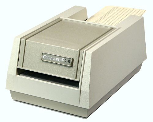 The card reader
The Compucorp R-8 card reader measures 150W x 230D x 100H (approx) and
weighs 2kg. Standard 12-row 80-column cards are inserted one at
a time through the slot at the front, and are drawn through and
stacked in the tray at the rear.
The drive mechanism uses a small 115V AC induction motor with a
die-cast and plastic reduction gearbox. One of the synthetic gears
is made of a material which has not stood the test of time, so the
reader is presently inoperable.
The reading mechanism uses two small incandescent lamps, an
acrylic light guide, and a set of twelve phototransistors and
discrete-component amplifiers. The top cover can be lifted off
to change the lamps.
The reader attaches to the rear of the calculator through a short
cable and a DB-25 connector. Warning: the cable and connector
also carry the 115V mains supply for the drive motor.
Circuitry
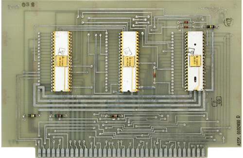 The logic boards
The logic circuitry is built on a set of seven double-sided boards
measuring 200mm wide x 140 high. The boards carry a total of 30 MOS-LSI
devices in 40, 28, and 16-pin ceramic packages, from the AMI "HTL"
chipset. The date codes in this machine range from May 1971 to the 3rd
week of January 1972. There are also about 50 discrete transistors
and 60 diodes, primarily in the keyboard and printer interfaces.
Power and logic connections are all made through the backplane,
while I/O signals to the keyboard, card reader, and printer are
taken through separate edge connectors on the fronts of the
appropriate boards.
Details and
photographs of all of the boards are
provided on separate pages.
Operation
Unfortunately the Operator's Manual for this machine has been
long discarded. The notes following have been prepared from personal
observations, and from comparisons with the operation of the
Compucorp 324. I would be grateful
for any further information, especially in regard to the angle
functions and the programming capabilities.
 The keyboard
Larger image (71kb)
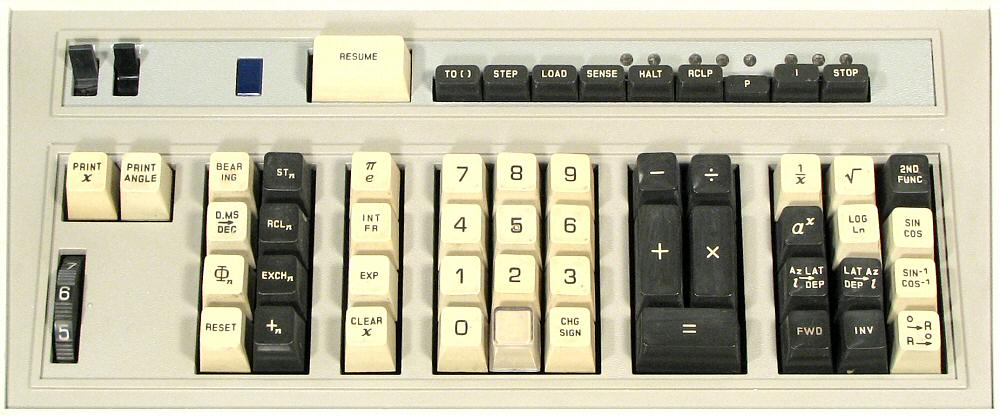
The keyboard
Larger image (71kb)
At the top left of the keyboard are the power switch and the
printer enable switch, with space for two more switches for use in
other models. Then comes a power indicator lamp, a large "Resume" key,
and a row of programming keys and indicators.
Below the first two switches are keys for "Print X" and "Print
Angle". The printer runs continuously and normally prints all entries,
operations, and intermediate results. The printer still continues to
run when disabled, but only prints specific results when requested
from the "Print" keys or the program.
The decimal point switch at the left-hand side selects from 0 to 9
decimal places. Settings 0 to 8 print 10 digits around a fixed
decimal point, with leading zeros supressed. "Overflow" is printed
when the available range is exceeded. When the switch is set to 9
the machine changes into "10+2" scientific notation, printing a full
10-digit mantissa with 9 decimal places and a 2-digit exponent.
The numeric and ASMD keys in the centre of the keyboard operate as
expected. There is a "Change Sign" key, a "Clear X" key, and an "EXP"
key for entering exponential notation. It is necessary to enter both
digits of the exponent, as 2 EXP 3 means 2^30 rather than 2^03. The
EXP key produces an immediate overflow if the decimal switch is set
to anything other than 9.
The four black keys to the left of the keyboard operate on the ten
internal storage registers. The keys are labelled
STOn, RCLn, EXCHn,
and +n, and function as expected. To the left of the
register keys is a "Reset" key and three angle keys. One key converts
degrees, minutes, and seconds to decimal degrees (and back), but the
functions of the "Bearing" and "Φn" keys are
not immediately obvious.
At the top right of the keyboard are keys for square roots, powers,
and reciprocals, which operate as expected.
The remainder of the yellow keys are marked with dual functions,
and operate in conjunction with the "2nd Func" key at the top right.
The operation is unusual in that pressing the labelled key calculates
both functions, displays the first in X, and stores the second in a
separate internal register. Pressing the "2nd Func" key switches
between the two registers. For example, "30 Sin/Cos" calculates both
sin 30 and cos 30 and displays 0.5. If you wanted cos 30, press "2nd
Func" to retrieve 0.866. "2nd Func" can be used repeatedly to switch
between the two results.
Dual-function keys are provided for Sin/Cos, inverse Sin/Cos,
common and natural logs, degrees to radians and inverse,
Integer/Fractional parts, and the constants π and e.
There is no Tan key - tangents can be calculated from the sequence
"X, Sin/Cos, Divide, 2nd Func, Equals".
The remaining four black keys at the lower right are basically
rectangular to polar conversions, customised to assist in
calculating a survey traverse. The first of the keys converts azimuth
and length ((Az,l) or (&Theta,r)) to latitude and
departure ((y,x) or north and east coordinates). The second
key calculates the inverse.
For example, "30 (Az,l) 2 Equals" displays the northing
(1.732 or root 3), and pressing "2nd Func" displays the easting (1.0).
(Surveyors measure azimuth clockwise from North). Pressing the FWD
or INV keys instead of Equals accumulates the north and east
increments from each step of a traverse into storage registers 0 and
1. The coordinates can be retreived at any stage of the traverse,
and should total to zero on returning to the starting point.
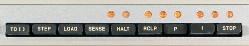 Programming
Programming is controlled by a set of push-buttons at the upper
right of the keyboard, along with the large "Resume" key near the top
centre. The eight neon lamps display the value of the program counter
or the instruction register, as selected by the "P" and "I" buttons.
The lamps are arranged in octal groupings, with the lenses labelled
in 4-2-1 sequence to assist in reading.
The program memory appears to be organised as 256 contiguous
locations, each holding one instruction or numeric value. Every
sixteenth location (20 octal) is directly addressable with the "TO[ ]"
(as in "go to") button, and can be used as a program entry point.
The first ten entry points at (octal) 0,20,40...220 can be addressed
from the keyboard with TO[0] to TO[9]. The remaining six at 240 to
360 are probably intended to be accessed through program cards, but
can also be obtained with non-numeric keys. For example, TO[CHS]
goes to address 260. The addresses are displayed in the lamps with
the "P" button down.
With the "I" button down, the lamps will display the instruction
opcode as each key is pressed. The keyboard opcodes are detailed in
a separate table. The opcodes appear
to be 6-bit (octal 000 to 077), with the keyboard using 43 of the
possible 64 combinations. Some of the keyboard opcodes appear to be
additive - for example, pressing 1/x (opcode 54) and numeral 2
(opcode 2) simultaneously registers as opcode 56 and calculates
square root rather than reciprocal. It is very likely that further
opcodes and addressing modes exist, for access only when programming
via the card reader.
To enter a program, the program counter is set to the desired entry
point with the TO[ ] key, the "LOAD" key is latched down, and the
program is entered from the keyboard or card reader. The program
counter advances as each instruction is registered. The "LOAD" key
is released on completion. To run the program, the entry point is set
again with the TO[ ] key and the "Resume" key is pressed. The "HALT"
key can be used as a program instruction to halt execution to allow
data entry from the keyboard. Execution is continued with the "Resume"
key. Several simple programs have been loaded and run successfully
from the keyboard. The "STEP", "SENSE", "RCLP", and "STOP" keys have
not been investigated in detail.
Resources for further information
Original text and images Copyright © John Wolff 2006-09.
Use at own risk; beware of errors; suggestions for improvement welcome.
Last Updated: 15 July 2009
Back to:
Home
Calculating Machines
Compucorp
Tech Index
 Compucorp Model 155 "Surveyor", S/N 3555019