John Wolff's Web Museum
The Casio AL-2000 Desk Calculator
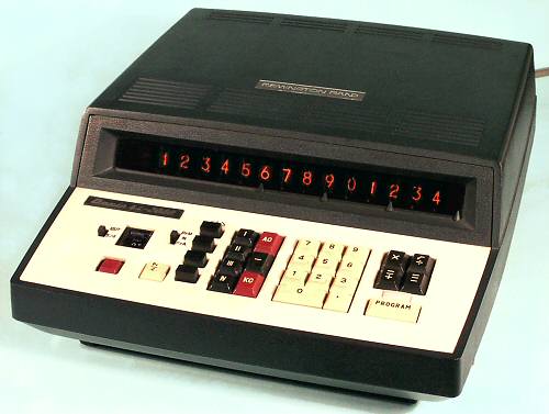
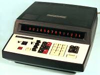 Casio Model AL-2000, S/N 205664
Functions: ASMD, square root, 4 memories
Programming: 30 steps, 14 instructions, no conditionals
Technology: DTL (MSI and discrete), magnetic core memory
Display: 14 digits, miniature Nixie tube
Dimensions: 340W x 400D x 150H
Weight: 6.8kg
Manufactured: Casio, Japan, 1970. (Sold by Remington)
The AL-2000 programmable desk calculator was introduced by the Casio
Computer Co Ltd of Tokyo, Japan, in November 1969. With
discrete-component DTL logic, MSI (medium-scale integration) chips, and
magnetic core memory, it represents a very early stage in the evolution
of programmable electronic calculators.
These notes are based on observations of one machine, and study of
several programs written and documented by the original owner.
Construction
The calculator is built in a substantial plastic case.
A metal card cage at the rear holds 5 printed circuit boards, stacked
one above the other. The double-sided boards have a component area of
11-3/4" x 7" (300 x 180mm). There are two 2x22-way double-sided
connectors on the longer edges, which plug in to a vertical backplane
across the centre of the machine.
The "CPU" occupies the three central boards, with the display driver
on the top board and the core memory on the bottom.
The keyboard uses glass reed switches operated by moving magnets
attached to the bottoms of the keys. The keyboard can be removed with
two screws to gain access to the power supply underneath. The power
supply has a voltage selector for 110/117/220/240V and is rated for
50/60Hz at 27VA.
Circuitry
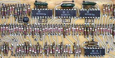
The circuitry of the AL-2000 uses a mixture of
discrete-component and SSI DTL logic. There are over 200 discrete
transistors, predominantly 2SA467, 2SC367, and 2SC371, and about 1000
diodes. There are about 90 SSI chips in 16-pin DIL packages,
predominantly Hitachi HD3106, with a small number of HD3103, 3104, and
3107. (Most board locations marked for HD3107 DIL chips are instead
fitted with HD713 chips in metal-can packages). There are 2 special LSI
chips (Philco SC1771 and SC1772) in 24-pin flat-packs. Apart from the
high-voltage supply for the display tubes, all of the circuitry operates
from a single -24VDC supply. The circuit boards are illustrated below.
 Display Driver Board
The metal-can transistors at the top left of the board are the
high-voltage anode drivers for the 14 Nixie tubes. The 10 cathode
drivers are at the bottom left. The other three metal-can transistors
are high-voltage drivers for the decimal point, minus, and "program"
indicators.
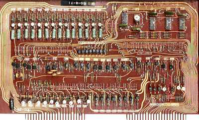
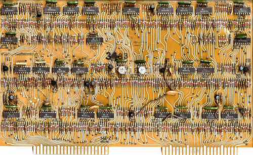
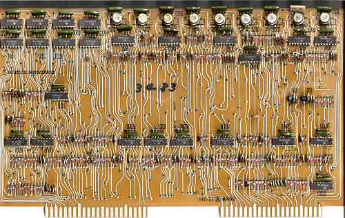
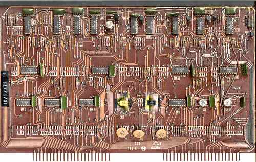
 Processor Boards
The three CPU boards are designated
MAIN1,
MAIN2, and
SUB.
The MAIN1 board has 28 IC packages, 14 transistors, and about 300
diodes. The illustration shows the typical packing density.
The green blobs that look like modern polyester capacitors ("greencaps")
are actually 4 or 6-way resistor arrays. The two LSI flat-pack chips
are located on the SUB board.
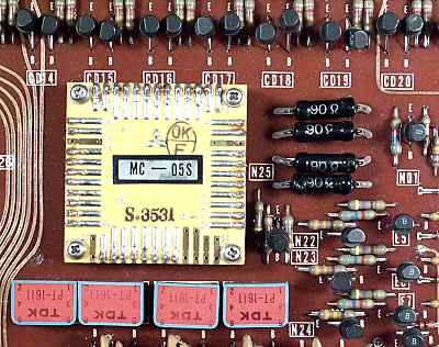
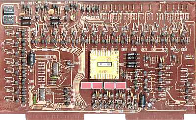 Core Memory Board
The core memory module "MC-05S" is
approximately 1-3/4" (45mm) square by 1/2" high, and carries a
Mitsubishi logo. The memory is organised physically as 16
columns x 8 rows x 4 planes, for a total of 512 bits. Logically, it
appears as 8 registers, each capable of holding 16 BCD (or 4-bit)
numbers. Four registers are used for the user memories, and two for
program storage. Being core memory, the contents are non-volatile, so that
programs and data are retained even when the calculator is switched off.
The memory driver circuits are implemented entirely with discrete
components. The matrix current sources and pulse transformers are at the
top left of the board, the row and column drivers are arranged above and
to the left of the core module, the inhibit drivers are at the lower
right, and the output is via the four red pulse transformers and the sense
amplifiers at the bottom. The diode array at the upper right is a
discrete-component version of a 4-to-16 decoder.
Keyboard Operation
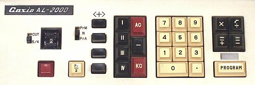
The un-labelled red button at the lower left of the keyboard is the
power switch. The other two red keys "KC" and "AC" are "Keyboard Clear"
and "All Clear". KC clears the keyboard and display; AC clears
everything except the core memory registers.
Addition and subtraction use the "=/+" and "=/-" keys in the function
keypad to the right of the numeric keys. The decimal point is positioned
according to the precision of the values entered. There is no
leading-zero supression.
Multiplication and division use the corresponding keys in the
function keypad, followed by either =/+ or =/-.
- =/- rounds or truncates the display according to the settings of the
roundoff switch and decimal selector at the left of the
keyboard, and aligns the display to the right.
- =/+ right-aligns the display with full decimal precision on
multiplication, and left-aligns it so as to display the maximum number
of decimal places on division.
Negative numbers can be entered by prefixing
them with the "-" key (located between the two Clear keys).
Square roots are calculated with the division key simply by omitting
the divisor. For example, 81 SQRT =/- calculates and displays
9.00
The four memory registers are accessed via the keys I to IV in the
centre of the keyboard. The same key is used for both "store" and
"recall", depending on the context. If pressed immediately after KC,
multiply, or divide it will "recall" the register contents; at any other
time it will "store" the contents of the display. A locking pushbutton
next to each memory key selects "constant" or "accumulate" modes:
- Button UP: Constant or store/recall mode. A "store" operation will
over-write the memory with the contents of the display. "Recall"
copies the memory contents back to the display, leaving the
memory register unchanged.
- Button DOWN: Accumulate mode. A "store" operation will add the
contents of the display to the value already in the register. "Recall"
transfers the total back to the display, leaving the memory register
cleared to zero.
The remaining keyboard controls ("Program" key and light, "Pr/2" key,
and mode switch) are related to programming, and are described in the
next section.
Programming
Any sequence of keyboard operations can be coded into a "program" and
entered into the memory for repeated execution. Being core memory, the
program is retained even when the calculator is turned off. There are no
conditional or branch instructions, but there is provision to implement
a loop counter for (manual) iteration. A large (8" x 13")
program sheet
printed on heavy paper assists the user to document the setup and
operation of the programs.
The programs are represented inside the machine as a sequence of up
to 30 single-digit (4-bit) operation codes (opcodes), which are stored
in two of the 16-digit core memory registers. The program sheet lists
the opcodes as follows:
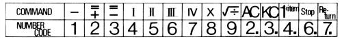
Opcode 0 represents "no operation", while 1 to 9 represent the
arithmetic and memory keys. Opcodes 10 to 15 are displayed (and entered)
as a single digit with a decimal point. Opcodes 2. and 3. are the AC and
KC keys, 4. enters digit 1 for use in an item counter, 6. pauses the
program to allow display or keyboard entry, while 7. halts execution
and returns the program counter to the beginning. Opcodes 1. and 5.
are not used. It is quite normal to have several digits showing decimal
points during program entry.
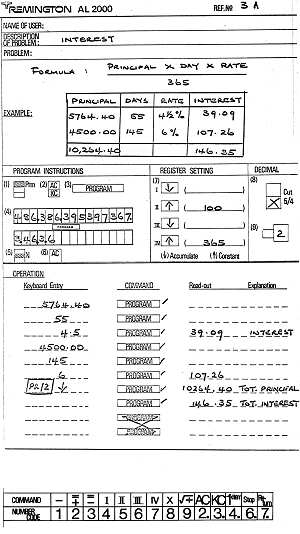
The following example is taken from an original user's AL-2000
programming card, and provides a good picture of the typical operation
of the machine.
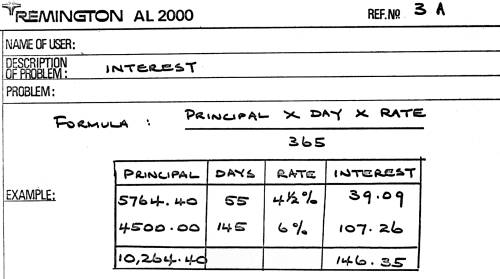
The top section of the card has space for a description and a
worked example of the problem - in this case, calculation and summation
of interest payments on a number of loans.
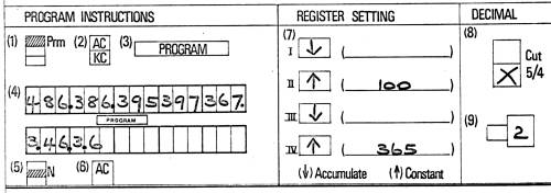
The second section contains the full details of the program
setup in graphical form via a sequence of numbered boxes.
- Set the mode switch to "PrM" (for "Program").
- Press both Clear keys.
- Press the Program key. This will display the first program register,
and allow any existing program to be over-written.
- Enter up to 15 program steps into the first program memory. The digits
are displayed and transferred into core as they are typed, but KC will
clear the entries
and start over. If all 15 steps are used, the first digit will scroll
off the left side of the display, but it will not be lost.
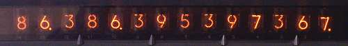
The illustration shows the display after entering the first line of the
example program, complete with multiple "decimal" points.
Press Program again to display and enter the second sequence of steps.
- Return the mode switch to "N" (for "Normal").
- Press AC. This completes the program entry.
- Next, set up the memory registers. In this program, registers I and
III are used to accumulate the principal and interest for a series of
calculations, so their mode switches are set down. Registers II and IV
are used to store the two constants 100 and 365. Their mode switches are
set up, and the constants are entered and stored from the keyboard (eg
KC 100 II KC 365 IV).
- Set the round-off switch to the 5/4 position.
- Set the decimal wheel to 2 for currency calculations. This completes
the setup of the machine.
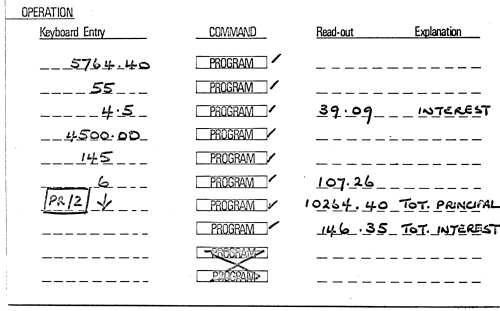
The third section contains the detailed instructions for
running the example program.
- Enter the principal for the first loan and press Program. The
program light comes on, and the machine pauses at the first "Stop"
instruction (6.) and waits for the next entry.
- Enter the number of days and press Program.
- Enter the rate and press Program. The machine calculates and
displays the interest, then adds the principal and interest to the
"accumulating" registers I and III. It halts execution at the "Return"
instruction (7.), turns off the Program light, and returns the program
counter to the beginning.
- Repeat steps 1 to 3 for as many interest calculations as required.
- When all calculations are complete, lock down the "Pr/2" key and
press Program. Execution now begins immediately after the
"Return" instruction, rather than at the beginning. The machine displays
Register I (total principal), then pauses with the Program light on.
- After noting the answer, press Program again to display the total
interest from Register III. Execution stops and the light goes out.
The example shows how the "Pr/2" key and the "Return" instruction
allow the program to be split into two related sections, or to store two
separate programs at the same time:
- With "Pr/2" UP, execution starts at the start and halts either at
the end or at a "Return" instruction.
- With "Pr/2" DOWN, execution begins immediately after the "Return"
instruction, and continues to the end. Any further "Return"s are ignored.
The fact that the split occurs at the end of the first program
register in the example is not significant - the split can be anywhere
in either register. Leading or trailing zeros in the program registers
have no effect, because opcode 0 is "No Operation".
The "PrA" position on the program mode switch is not used or
referenced in any of the program sheets obtained from the original
owner.
Original text and images Copyright © John Wolff 2002-18.
Use at own risk; beware of errors; suggestions for improvement welcome.
Last Updated: 15 April 2018
Back to:
Home
Calculating Machines
Casio
 Casio Model AL-2000, S/N 205664